
TB 9-6625-2293-35
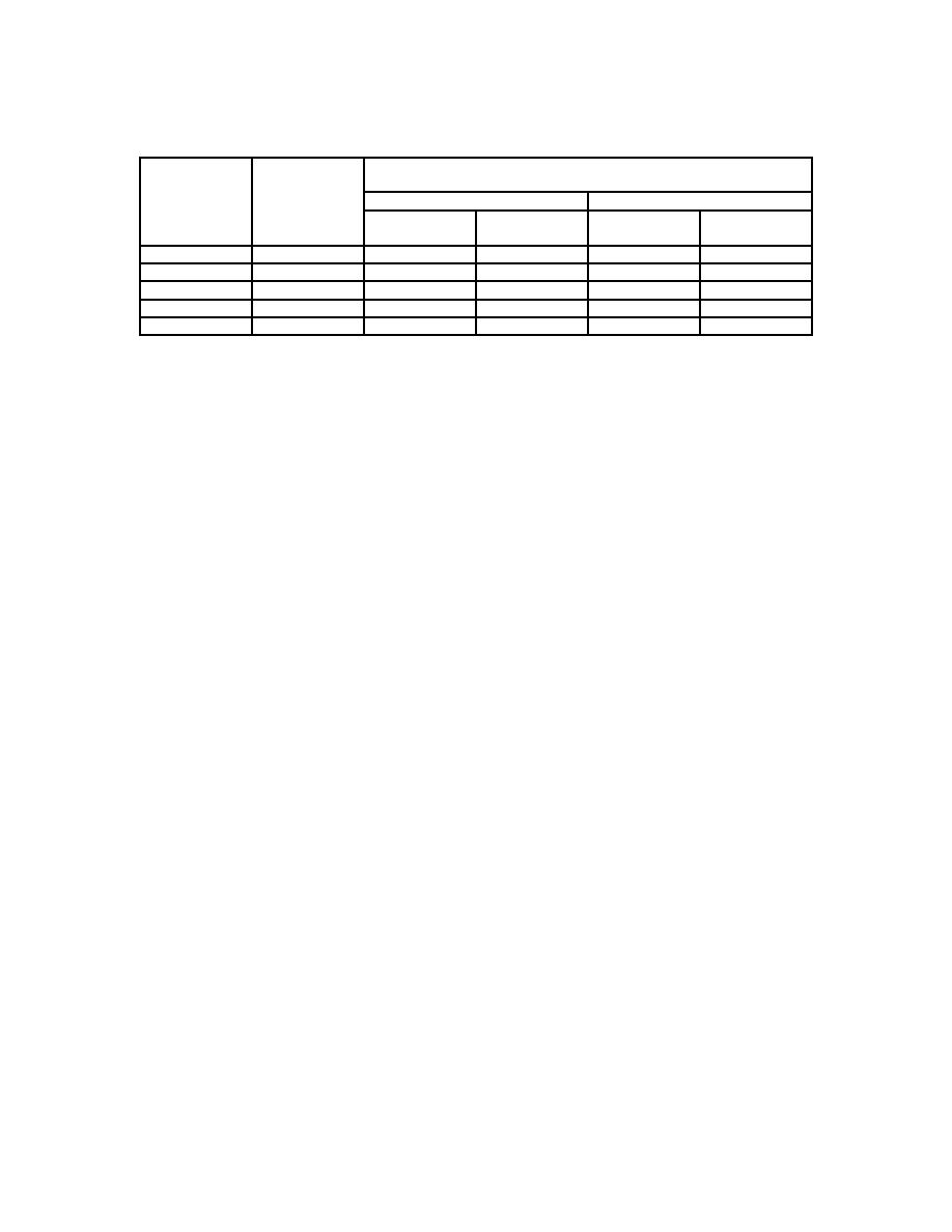
Table 7. B Trigger Level Readout - Continued
Test
Test instrument trigger level readout indications
instrument
- Peak
VOLTS/DIV
+ Peak
switch
output
settings
settings
Min
Max
Min
Max
200
mV
1.0 V
0.90 V
1.10 V
-70 mV
70 mV
500
mV
2.0 V
1.78 V
2.22 V
-.14 V
.14 V
1.0 V
5.0 V
4.50 V
5.50 V
-.35 V
.35 V
2.0 V
10.0 V
9.0 V
11.0 V
-0.7 V
0.7 V
5.0 V
20.0 V
17.8 V
22.2 V
-1.4 V
1.4 V
(14) Reduce outputs to minimum and disconnect equipment setup.
(15) Press TRIGGER SLOPE pushbutton for + (plus).
(16) Set TRIGGER COUPLING switch down to AC.
(17) Set TRIGGER MODE switch up to RUN AFT DLY then press A/B TRIG
pushbutton and set TRIGGER MODE switch up to AUTO LVL.
(18) Set CH 1 VOLTS/DIV switch to 10 mV and A SWP SEC/DIV switch to 10 ms
(knob locked).
(19) Connect oscilloscope calibrator SOURCE/MEASURE CHAN 1 and 2 outputs to
TI CH 1 and 2 inputs respectively.
(20) Set oscilloscope calibrator for a CHAN 1, WAVE GEN (WAVE sine) mode
output 35 mV at a 60 Hz frequency, and adjust amplitude for 3.5 divisions of vertical
display on TI.
(21) Set CH 1 VOLTS/DIV switch to 100 mV and adjust TRIGGER LEVEL control
for a stable display. If a stable display cannot be obtained, perform b below.
NOTE
Set A SWP SEC/DIV switch and press X10 MAG pushbutton
as necessary to obtain a well-defined display of test signal.
(22) Insert a 50 Ω feedthrough termination into connection.
(23) Set CH 1 VOLTS/DIV switch to 10 mV and press 20 MHz BW LIMIT to off.
(24) Set oscilloscope calibrator for a CHAN 1, LEVEL SINE mode output of 50 MHz
and adjust amplitude for 3.5 divisions of vertical display on TI.
(25) Set CH 1 VOLTS/DIV switch to 100 mV and adjust TRIGGER LEVEL control
for a stable display. If a stable display cannot be obtained, perform b below.
(26) Remove 50 Ω feedthrough termination from connection.
(27) Set TRIGGER COUPLING switch up to DC and repeat technique of (20)
through (26) above.
(28) Set oscilloscope calibrator for a CHAN 1, LEVEL SINE mode output of
500 MHz and adjust amplitude for 1.0 division of vertical display on TI.
(29) Adjust TRIGGER LEVEL control for a stable display. If a stable cannot be
obtained perform b below.
11

