
TB 9-6625-2294-24
(14) Repeat technique of (11) through (13) above for remaining rows listed in table 4.
Oscilloscope calibrator err display indications will be within limits specified in table 4. If
not, perform b below.
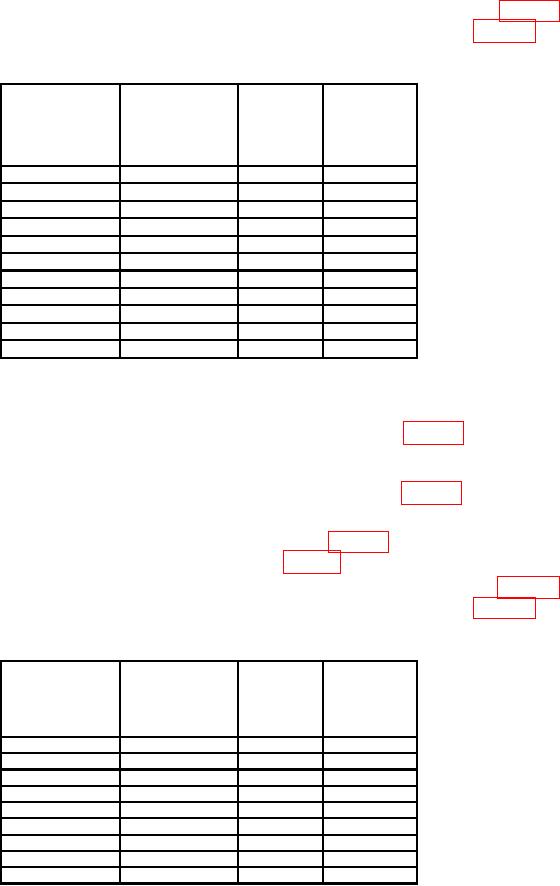
Table 4. CH 2 Vertical Gain
Oscilloscope
Test
instrument
Oscilloscope
calibrator
err display
display
Test instrument
calibrator
VOLTS/DIV
VOLTAGE
indications
amplitude
switch settings
output settings
(%)
divisions
2
mV
10
mV
5
2
5
mV
20
mV
4
2
10
mV
50
mV
5
2
20
mV
0.1 V
5
2
50
mV
0.2 V
4
2
100
mV
0.5 V
5
2
200
mV
1.0 V
5
2
500
mV
2.0 V
4
2
1.0 V
5.0 V
5
2
2.0 V
10.0 V
5
2
5.0 V
20.0 V
4
2
(15) Press CH 2 input pushbutton to select 50
DC.
(16) Perform steps (a) through (d) below:
(a)
Set oscilloscope calibrator output as listed in first row of table 5.
Set oscilloscope calibrator output frequency to 1 kHz.
(b)
Set oscilloscope calibrator SCOPE Z to 50 .
(c)
Set TI CH 2 VOLTS/DIV switch as listed in first row of table 5.
(d)
(17) Rotate knob located below EDIT FIELD pushbutton on oscilloscope calibrator to
obtain TI display amplitude divisions as listed in first row of table 5. Oscilloscope calibrator
err display will be within limits specified in first row of table 5. If not, perform b below.
(18) Repeat technique of (16) and (17) above for remaining rows listed in table 5.
Oscilloscope calibrator err display indications will be within limits specified in table 5. If
not, perform b below.
Table 5. CH 2 50
Input Gain
Oscilloscope
Test
calibrator
instrument
Oscilloscope
err display
display
calibrator
Test instrument
indications
amplitude
VOLTAGE
VOLTS/DIV
(%)
divisions
output settings
switch settings
2
mV
10
mV
5
3
5
mV
20
mV
4
3
10
mV
50
mV
5
3
20
mV
0.1 V
5
3
50
mV
0.2 V
4
3
100
mV
0.5 V
5
3
200
mV
1.0 V
5
3
500
mV
2.0 V
4
3
1.0 V
5.0 V
5
3
8

