
TB 9-6625-2294-24
between leading edge of B sweep time markers (2 peaks) will be as specified in first row of
table 18. If not, perform b below.
(50) Repeat technique of steps (47) through (49) above for remaining row listed in
table 18. Division limits for horizontal distance between leading edges of B sweep time
markers will be as specified in table 18. If not, perform b below.
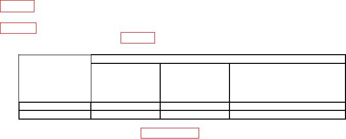
Table 18. Delayed Sweep Delta Time X10 MAG off (TRACK)
Test instrument
Division limits for
horizontal distance
Oscilloscope
between leading edges of
calibrator
B sweep time markers
MARKER
B SWP SEC/DIV
A SWP SEC/DIV
( )
output settings
switch setting
switch settings
S/D
s
1
1
10 ns
3.4
S/D
s
5
5
50 ns
3.4
b. Adjustments. Refer to SECTION IV below.
11. Bandwidth
a. Performance Check
(1) Set A SWP SEC/DIV switch for 50 s (knob in).
(2) Set CH 1 VOLTS/DIV switch to 20 mV.
(3) Press corresponding pushbuttons for indications as listed in (a) through (f) below.
VERTICAL MODE CH 1 on.
(a)
VERTICAL MODE CH 2, CH 3, and CH 4 off.
(b)
CH 1 and CH 2 input coupling pushbuttons for 1 M
DC.
(c)
TRIGGER SOURCE for VERT CH 1.
(d)
t off.
(e)
TRACK/INDEP for INDEP (not illuminated).
(f)
(4) Ensure oscilloscope calibrator SOURCE/MEASURE CHAN 1 is connected to TI
CH 1 using a 50 feedthrough termination.
(5) Set oscilloscope calibrator LEVEL SINE output frequency to 50 kHz and output
initially for 120 mV. Rotate knob located below EDIT FIELD pushbutton for 6 divisions of
display on TI.
(6) Sweep oscilloscope calibrator frequency to 350 MHz. TI display will be 3.5
divisions in amplitude or greater throughout sweep; if not, perform b below.
(7) Press TRIGGER SOURCE lower pushbutton to CH 2.
(8) Press VERTICAL MODE CH 1 pushbutton off and CH 2 on.
(9) Set CH 2 VOLTS/DIV switch to 20 mV.

