
TB 9-6625-2294-35
(a) VERTICAL MODE CH 1 to on, and VERTICAL MODE CH 2, CH 3, and
CH 4 off.
(b)
20 MHz BW LIMIT on.
CH 1 and CH 2 input coupling to 1 MΩ DC.
(c)
(d)
TRIGGER coupling to DC.
(e)
TRIGGER SOURCE to VERT CH 1.
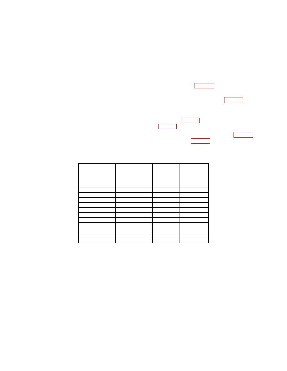
(4) Set CH 1 VOLTS/DIV switch as listed in first row of table 3 and set A SWP
SEC/DIV switch to 1 ms.
(5) Set oscilloscope calibrator VOLTAGE output as listed in first row of table 3 and
frequency to 1 kHz.
(6) Rotate knob located below EDIT FIELD pushbutton on oscilloscope calibrator to
obtain TI display amplitude divisions as listed in first row of table 3. Oscilloscope calibrator
(7) Repeat technique of (4) through (6) above for remaining rows listed in table 3.
Oscilloscope calibrator err display indications will be as listed in table 3 if not, perform b
below.
Oscilloscope
Test
calibrator
instrument
Oscilloscope
err display
display
calibrator
Test instrument
indications
amplitude
VOLTAGE
VOLTS/DIV
(%)
divisions
output settings
switch settings
2
mV
10
mV
5
2
5
mV
20
mV
4
2
10
mV
50
mV
5
2
20
mV
0.1 V
5
2
50
mV
0.2 V
4
2
100
mV
0.5 V
5
2
200
mV
1.0 V
5
2
500
mV
2.0 V
4
2
1.0 V
5.0 V
5
2
2.0 V
10.0 V
5
2
5.0 V
20.0 V
4
2
(8) Press TRIGGER SOURCE pushbutton to select CH 2.
(9) Press VERTICAL MODE pushbuttons CH 2 on, and CH 1 off.
NOTE
Press oscilloscope calibrator CHANNEL pushbutton. Next
press blue soft pushbutton located below CHAN 2 on
oscilloscope calibrator when SELECT CHANNEL is displayed.
7

