
TB 9-6625-2294-35
(17) On oscilloscope calibrator rotate knob located below EDIT FIELD pushbutton to
align 10th time marker with 10th vertical graticule line. Oscilloscope calibrator err display
limits will be as listed in second row of table 13, if not perform b below.
(18) Repeat technique of (13) through (17) above for remaining rows listed in table
below.
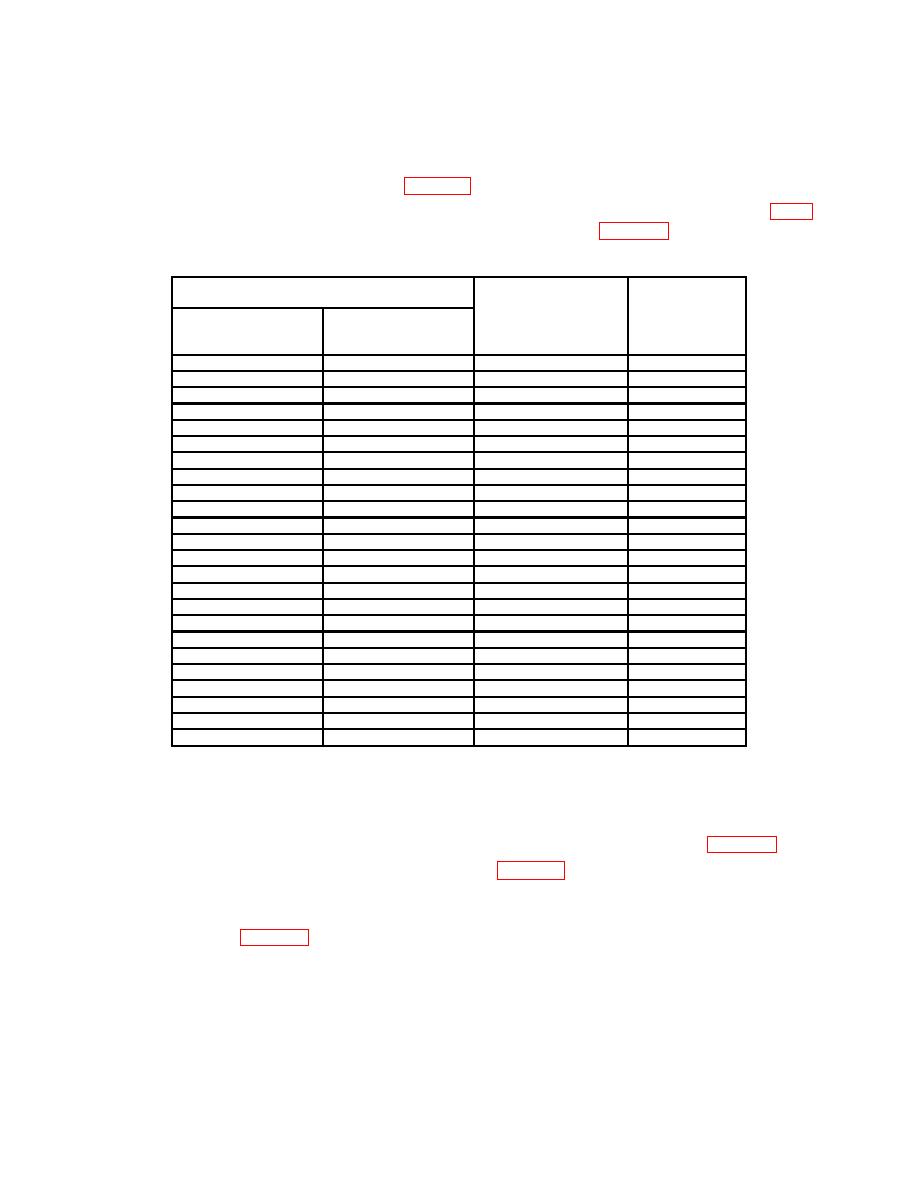
Table 13. B SWP Timing
Oscilloscope
Test instrument
Oscilloscope
calibrator
err
calibrator
display limits
MARKER
B SWP SEC/DIV
A SWP SEC/DIV
(%)
output settings
switch settings
switch settings
S/D
51
ms
500
1.95
10
ns
5
ns
5
nS/D
1.75
2
20
ns
10
ns
10
nS/D
1.75
50
ns
20
ns
20
nS/D
1.75
100
ns
50
ns
50
nS/D
1.75
200
ns
100
ns
100
nS/D
1.75
500
ns
200
ns
200
nS/D
1.75
s
1
500
ns
500
nS/D
1.75
s
s
S/D
2
1
1
1.75
s
s
S/D
5
2
2
1.75
s
s
S/D
10
5
5
1.75
s
s
S/D
20
10
10
1.75
s
s
S/D
50
20
20
1.75
s
s
S/D
100
50
50
1.75
s
s
S/D
200
100
100
1.75
s
s
S/D
500
200
200
1.75
s
S/D
1
ms
500
500
1.75
2
ms
1
ms
1
mS/D
1.75
5
ms
2
ms
2
mS/D
1.75
10
ms
5
ms
5
mS/D
1.75
20
ms
10
ms
10
mS/D
1.75
50
ms
20
ms
20
mS/D
1.75
100
ms
50
ms
50
mS/D
1.75
10
ms
5
ms
.5
mS/D
2.25
3
1Press
X10 MAG pushbutton on.
2
Press X10 MAG pushbutton off.
3
Press X10 MAG pushbutton on and after this step press X10 MAG off.
(19) Press TI ∆t pushbutton on (cursors on crt).
(20) Set oscilloscope calibrator MARKER output as listed in first row of table 14.
(21) Set A SWP SEC/DIV switch as listed in table 14 (knob in).
(22) Adjust ∆REF OR DLY POS control to align one cursor with 2d time marker and
∆ control to align other cursor with 10th time marker. If ∆t readout indication is not within
limits as listed in table 14, perform b below.
19

