
TB 9-6625-2294-35
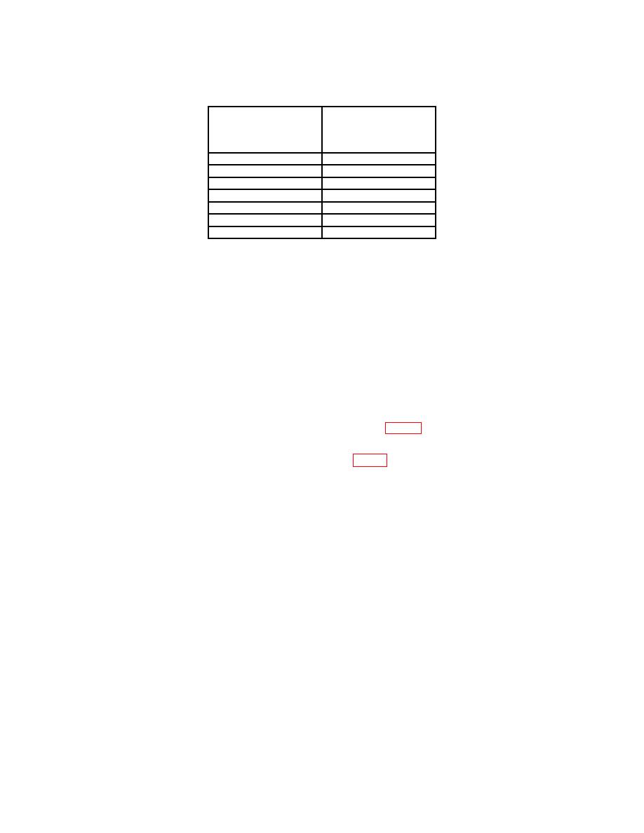
Test instrument
CAL 02
Oscilloscope calibrator
step numbers
VOLTAGE output
settings
123, 124
.5 V
1
125
.2 V
126
.1 V
127
50 mV
128
20 mV
129
1V
1302
10 V
When stop 123 is performed, step 124 is automatically done.
1
No indication of step 124 will be shown unless a LIMIT
error is encountered.
2When step 130 is performed, step 131 is automatically done.
No indication of step 131 will be shown unless a LIMIT
error is encountered.
(13) Press and release upper TRIGGER COUPLING pushbutton.
TI will
automatically step from 130 to 142. Display readout will indicate: CONNECT SIGNAL
TO CH 1, (step) 142, 50 mV, and BWL.
(14) Move connection from CH 2 to CH 1.
(15) Set oscilloscope calibrator VOLTAGE output to 50 mV.
(16) Press and release upper TRIGGER COUPLING pushbutton.
Wait
approximately 10 seconds for automatic calibration of ∆V cursors. Display readout will
horizontal cursors (R).
(17) Adjust VERTICAL CENTERING R639 (fig. 1) to align cursors with 0 percent
and 100 percent graticule lines (R).
(18) Press and release upper TRIGGER COUPLING pushbutton. Self calibration
will continue 15 to 45 seconds. Display will indicate: DIAGNOSTIC. PUSH AB TRIG TO
EXIT.
20. CAL 03 - Triggering
a. Performance Check
(1) Press upper TRIGGER MODE pushbutton to CAL 03 (bottom left of display).
(2) Press and release upper TRIGGER COUPLING pushbutton.
(3) TI will automatically step from 200 to 214 and stop at 215. Display indicates:
CH 1, 500 mV, (step) 215.
(4) Connect oscilloscope calibrator SOURCE/MEASURE CHAN 1 to CH 1.
(5) Set oscilloscope calibrator VOLTAGE output to 0.5 V at 1 kHz.

