
TB 9-6625-2295-24
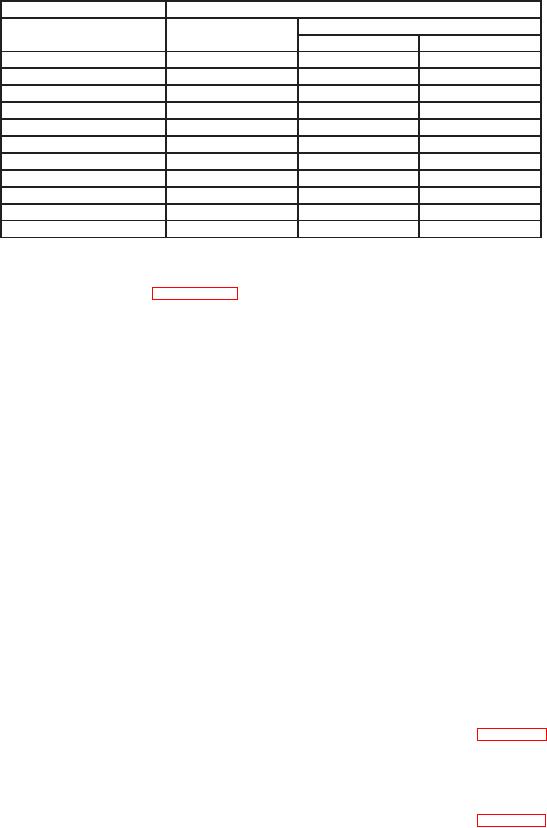
Table 9. 'V With Cursors
Oscilloscope calibrator
Test instrument
VOLTS/DIV
V readout indications
settings
Output settings
Min
Max
10 mV
2 mV
9.81 mV
10.2
mV
20 mV
5 mV
19.6
mV
20.4
mV
50 mV
10 mV
49.0
mV
50.9
mV
0.1 V
20 mV
98.1
mV
102.0
mV
0.2 V
50 mV
196
mV
204
mV
0.5 V
100 mV
490
mV
509
mV
1 V
200 mV
0.981 V
1.02
V
2 V
500 mV
1.96 V
2.04
V
5 V
1.0 V
4.90 V
5.09
V
10 V
2.0 V
9.81 V
10.2
V
20 V
5.0 V
19.6
V
20.4
V
(46) Reduce all outputs to minimum.
b. Adjustments. Perform Section IV below.
9. Triggering
a. Performance Check
(1) Press corresponding pushbutton for indications as listed in (a) through (c) below:
(a) TRIGGER MODE to NORM.
(b) CH 1 and CH 2 input coupling to 1 M: DC.
(c) 'V to off (cursors off).
(2) Position controls as listed in (a) through (c) below:
(a) CH 1 VOLTS/DIV switch to 5 mV.
(b) CH 1 and CH 2 VOLTS/DIV VAR controls cw to detent.
(c) TRIGGER LEVEL control to midrange.
(3) Set oscilloscope calibrator for a CHAN 1, VOLTAGE mode output of 20 mV at 1
kHz.
NOTE
Combine steps (4) and (5) below to avoid resetting standards.
(4) Adjust TRIGGER LEVEL control for most positive voltage that produces a
barely triggered display when selecting + and - SLOPE. If A TRIGGER LEVEL readout
indication is not within limits specified in + peak column in first row of table 10, perform
b below.
(5) Adjust TRIGGER LEVEL control for most negative voltage that produces a
barely triggered display when selecting + and - SLOPE. If A TRIGGER LEVEL readout
indication is not within limits specified in - peak column in first row of table 10, perform
b below.

