
TB 9-6625-2295-35
(6) Rotate oscilloscope calibrator knob below EDIT FIELD pushbutton to adjust
amplitude for 5 divisions of deflection on TI. If oscilloscope calibrator err display does not
indicate within limits specified in first row of table 3, perform b below.
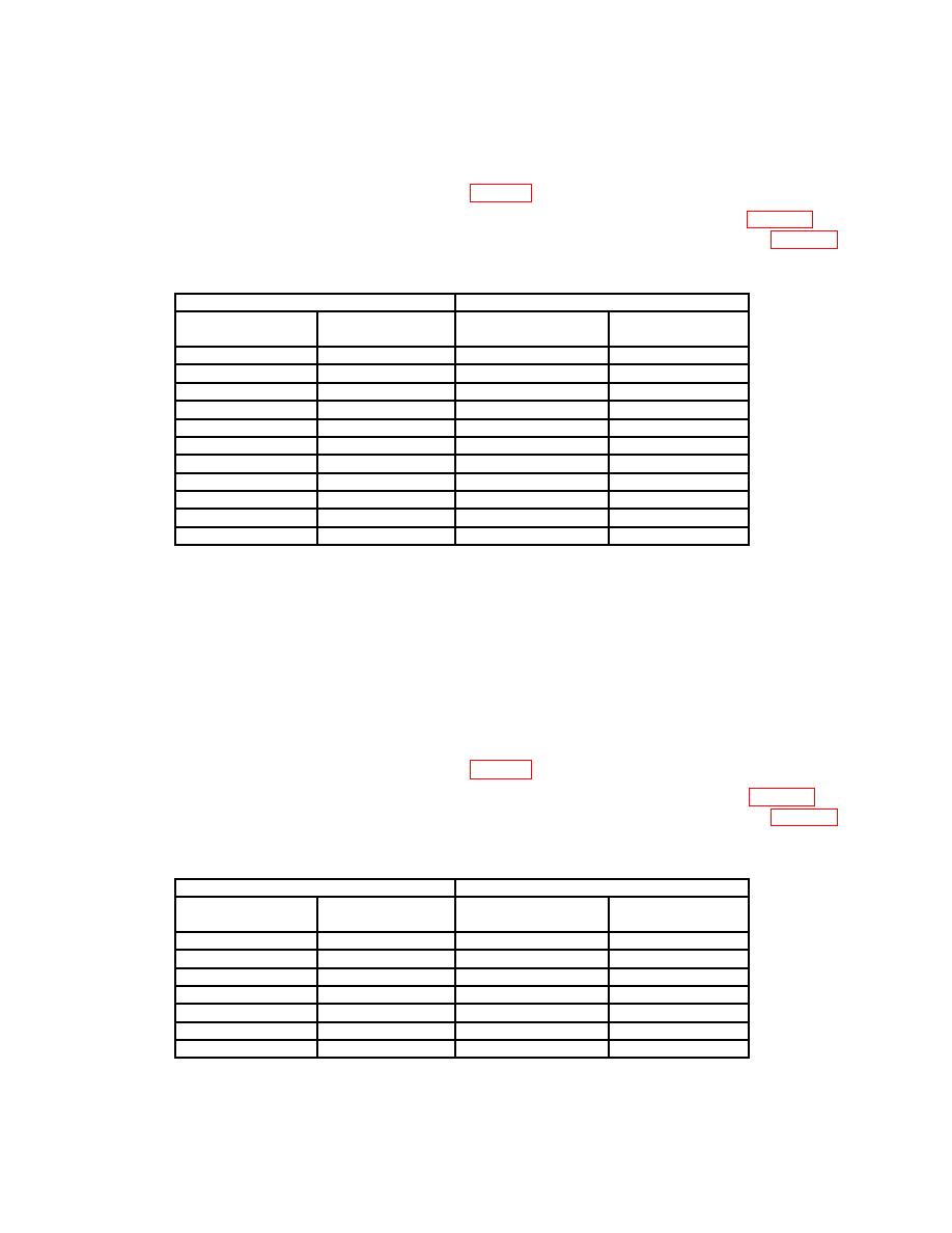
(7) Repeat technique of (4) through (6) above for settings listed in table 3. If
oscilloscope calibrator err display does not indicate within limits specified in table 3,
perform b below.
Test instrument
Oscilloscope calibrator
VOLTS/DIV
Vertical deflection CHAN 1 VOLTAGE
err display
switch settings
output
(divisions)
indication (%)
2 mV
5
10 mV
2
5 mV
4
20 mV
2
10 mV
5
50 mV
2
20 mV
5
100 mV
2
50 mV
4
200 mV
2
100 mV
5
0.5 V
2
200 mV
5
1.0 V
2
500 mV
4
2.0 V
2
1.0 V
5
5.0 V
2
2.0 V
5
10.0 V
2
5.0 V
4
20.0 V
2
(8) Reduce all outputs to minimum.
(9) Press TRIGGER SOURCE lower pushbutton to select CH 2.
(10) Press VERTICAL MODE pushbuttons CH 2 on and CH 1 off.
(11) Set CH 2 VOLTS/DIV switch to 2 mV.
(12) Set oscilloscope calibrator for a CHAN 2, VOLTAGE mode output of 10 mV at
1 kHz frequency.
(13) Rotate oscilloscope calibrator knob below EDIT FIELD pushbutton to adjust
amplitude for 5 divisions of deflection on TI. If oscilloscope calibrator err display does not
indicate within limits specified in first row of table 4, perform b below.
(14) Repeat technique of (11) through (13) above for settings listed in table 4. If
oscilloscope calibrator err display does not indicate within limits specified in table 4,
perform b below.
Test instrument
Oscilloscope calibrator
VOLTS/DIV
Vertical deflection CHAN 2 VOLTAGE
err display
switch settings
output
(divisions)
indication (%)
2 mV
5
10 mV
2
5 mV
4
20 mV
2
10 mV
5
50 mV
2
20 mV
5
0.1 V
2
50 mV
4
0.2 V
2
100 mV
5
0.5 V
2
200 mV
5
1.0 V
2
7

