
TB 9-6625-2295-35
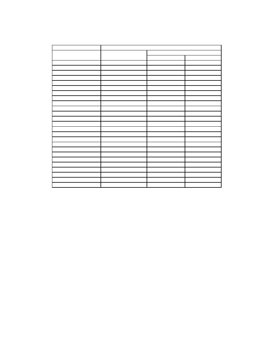
Oscilloscope calibrator
Test instrument
A SWP SEC/DIV
MARKER mode
∆t indication limit
output
settings
Min
Max
5 ns
5 ns
39.65 ns
40.35 ns
10 ns
10 ns
79.30 ns
80.70 ns
20 ns
20 ns
158.6
ns
161.4 ns
50 ns
50 ns
396.5
ns
403.5 ns
100 ns
100 ns
793.0
ns
807.0
ns
200 ns
200 ns
1586
ns
1614
ns
500 ns
500 ns
3965
ns
4035
ns
1 s
1 s
7.93 s
8.07 s
2 s
2 s
15.86 s
16.14 s
5 s
5 s
39.65 s
40.35 s
10 s
10 s
79.30 s
80.70 s
20 s
20 s
158.60 s
161.4
s
50 s
50 s
396.5
s
403.5
s
100 s
100 s
793.0
s
807.0
s
200 s
200 s
1586.0
s
1614.0
s
500 s
500 s
3965
s
4035
s
1 ms
1 ms
7.930 ms
8.070 ms
2 ms
2 ms
15.860 ms
16.140 ms
5 ms
5 ms
39.65 ms
40.35 ms
10 ms
10 ms
79.30 ms
80.70 ms
20 ms
20 ms
158.60 ms
161.40 ms
50 ms
50 ms
396.5 ms
403.5 ms
100 ms
100 ms
793.0 ms
807.0 ms
200 ms
200 ms
1578
ms
1622
ms
500 ms
500 ms
3945
ms
4055
ms
(20) Set A SWP SEC/DIV switch to 10 ns and B SWP SEC/DIV switch to 5 ns
(knob out).
(21) Press corresponding pushbuttons for indications as listed in (a) through (d)
below.
(a)
TRIGGER SOURCE to VERT CH 1.
∆t to off (DLY readout).
(b)
(c)
A/B TRIG for B TRIGGER and TRIGGER MODE to RUN AFT DLY.
(d)
Xl0 MAG on.
(22) Set oscilloscope calibrator for a CHAN 1, MARKER mode output of 10 ns.
(23) Set TI VOLTS/DIV switch as required for a display of 3 to 6 divisions and
adjust ∆ REF OR DLY POS control for DLY readout of 10.64 ns.
(24) Adjust TRIGGER LEVEL control as required for a stable display.
(25) Adjust ⇦POSITION⇨ control cw until the trace stops moving, then ccw to
position leading edge of the 2d time marker near graticule center.
(26) Set oscilloscope calibrator for a CHAN 1, MARKER mode output of 5 ns.
(27) Press ∆t pushbutton to obtain ∆t display and push in SEC/DIV knob for B SWP
only.
17

