
TB 9-6625-2296-24
display Reading equal to TI indication. Calibrator control display Error indications will be
within limits specified in table 9.
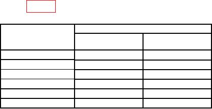
Table 9. Ohms.
Calibrator
Test instrument
Output
Error indications
range settings
settings
(%)
Ω1
200
100
10.1
Ω
2
kΩ
1
kΩ
10.1
20
kΩ
10
kΩ
10.1
2
200
kΩ
100
kΩ
10.1
2
MΩ
1
MΩ
10.1
20
MΩ
10
MΩ
10.1
Set calibrator 2 wire Comp to ON.
1
Set calibrator 2 wire Comp to OFF.
2
b. Adjustments. No further adjustments can be made.
13. Generator Output Level
a. Performance Check
(1) Press key sequence listed in (a) through (f) below:
(a) MODE MTRS ..........................
Meters Menu
(b) AUX (F6) ..................................
Auxiliary Function Menu
(c) MEMORY RCL .......................
Recall
(d) FIELD SELECT ..................
Highlight 10. Factory Defaults
(e) DATA ENTRY ENTER ..........
Factory Defaults recall
NOTE
Assure highlighted area indicates YES before proceeding.
(f) DATA ENTRY ENTER ..........
Factory Defaults restored
NOTE
If necessary, perform measuring receiver zero and calibrate.
(2) Connect measuring receiver sensor module to TI T/R IN/OUT.
(3) Press key sequence listed in (a) through (h) below:
(a) MODE RF GEN ......................
RF Gen Display
(b) SETUP .....................................
Gen Menu
(c) DATA ENTRY 5 ......................
RF Gen Setup
(d) DATA ENTRY 2 ......................
RF Gen Level
(e) DATA ENTRY 0 ENTER .......
0 dBm
(f) DATA ENTRY 1 ......................
RF Gen Freq

