
TB 9-6625-2296-35
(11) Reduce signal generator and RF power amplifier outputs to minimum and
disconnect equipment setup.
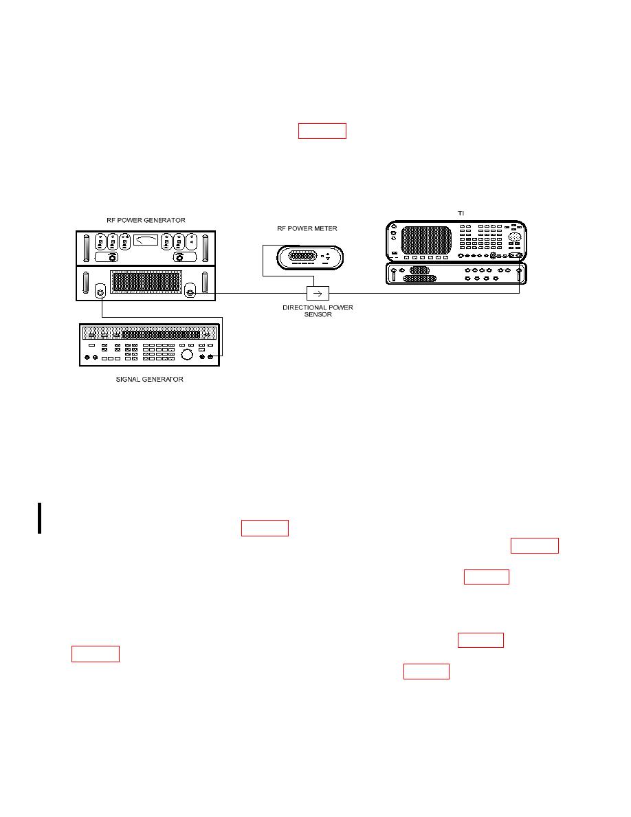
(12) Connect equipment as shown in figure 7.
NOTE
Use directional power sensor model 4021.
(13) Press Range (F1) and DATA SCROLL arrow keys to select 20 mW range and
press Zero (F4) key. Press DATA ENTRY ENTER key when Zero submenu appears.
Adjust DATA SCROLL knob to slect 1 W range and press the DATA ENTRY ENTER
key.
power amplifier gain to minimum then adjust gain and signal generator output for RF
power meter indication listed in table 14 corresponding to 1W range.
(15) If the TI does not indicate within minimum maximum limits listed in table 14
for range being checked, perform b below.
(16) Repeat (14) for 2, 5, 10, 20, 50, 100, and 200 W ranges listed in table 14.
(17) Reduce signal generator and RF power amplifier outputs to minimum and
replace directional power sensor model 4021 with model 4022. Repeat (14) and (16) above
for a frequency of 400 MHz.
(19) If the TI does not indicate within limits specified in table 15 perform b below.
44 CHANGE 1

