
TB 9-6625-2309-24
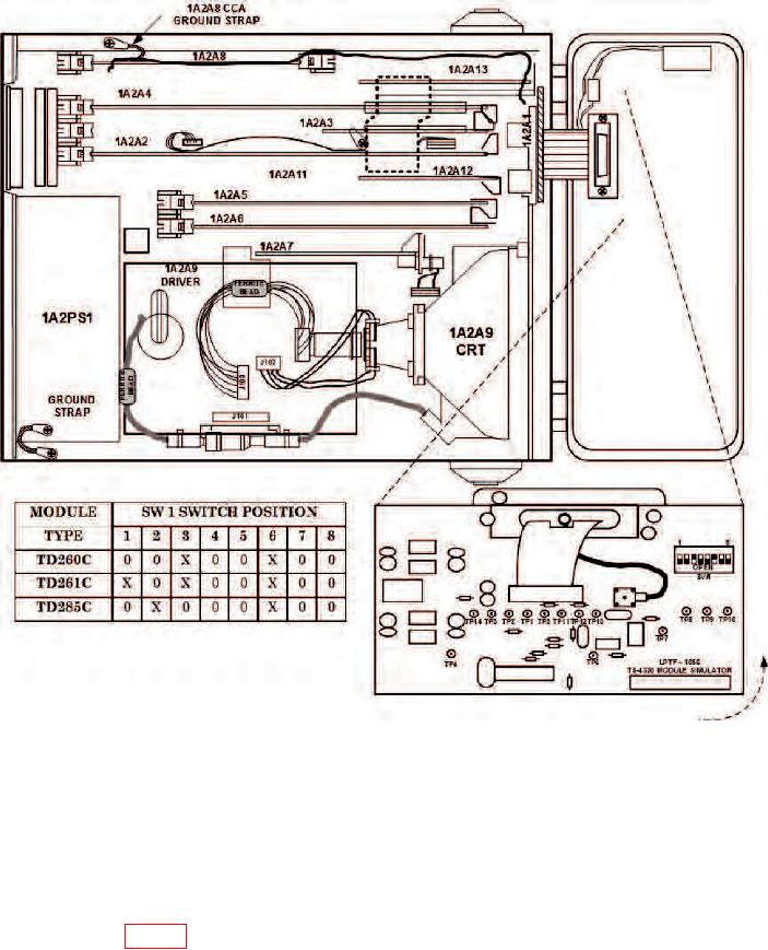
Figure 15. TS-4320(P)/G board locations and optical module simulator.
(4) Set ON-OFF switch to ON.
NOTE
Allow 15 minutes for TI to warm-up before making voltage
measurements.
IC U71, pin 9 (fig. 16). Frequency will be between 24.99925 to 25.00075 MHz; if not, repair
is indicated.
26

