
TB 9-6625-2316-24
Figure 1. Test and connection points and adjustments.
(8) Press the ADVANCE pushbutton once; circuit 01 will be under test, FAULT
light and TEST light should be on.
(9) Set resistance standard No. 2 for 20.0
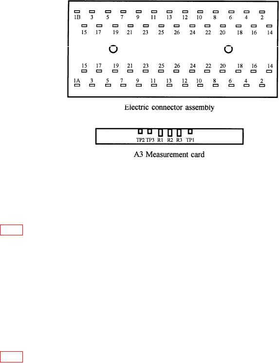
and connect between pins 1A and 1B
(fig. 1) of the electric connector assembly (connected to end of adapter cable).
(10) Monitor dc voltage at TP2 with the multimeter using the cage as the ground
reference.
(11) Adjust R1 so that the voltage at TP2 is about 2.5 V (this voltage is unstable and
just between the high and low crossover points) (R).
(12) Press the RESET pushbutton and disconnect resistance standard No. 2.
(13) Set FUNCTION switch to IR (0.1M).
(14) Set AUTO/SINGLE switch to SINGLE.
(15) Press the ADVANCE pushbutton once; the TEST light should be on and the
FAULT light should be off.
(16) Set resistance standard No. 2 for 100 k and connect between pins 1A and 1B
(fig. 1) of the electric connector assembly (connected to end of adapter cable).
(17) Use the multimeter to measure dc voltage at TP1, with the cage as ground
reference. The voltage should be about 900 mV; record the exact reading.
(18) Monitor the dc voltage reading at TP3; if it is different from that at TP1, adjust
R3 so that voltage at TP3 is the same ( 1 mV) as that at TP1 (R).
(19) Press the RESET pushbutton and disconnect resistance standard No. 2.
5

