
TB 9-6625-2321-24
b. Adjustments. Perform the procedure as outlined in 8 b above.
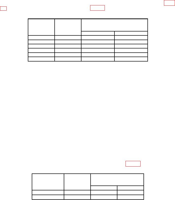
10. Resistance
a. Performance Check. Set calibrator output and TI controls to values listed in table
Table 5. Resistance
ange
alibrator
pushbutton
output
Test instrument indications
sRttings
e
settings
C
Min
Max
200
190
188.00
192.00
2
k
1.90 k
1.8800 k
1.9200
k
20
k
19.0 k
18.800
k
19.200
k
200
k
190
k
188.00
k
192.00
k
2
M
1.90 M
1.8800 M
1.9200
M
20
M
19.0 M
18.800
M
19.200
M
b. Adjustments. Perform the procedure as outlined in 8 b above.
11. Dc Current
a. Performance Check
(1) Disconnect TI red (+) and black (-) test probes from calibrator OUTPUT HI and
LO terminals.
(2) Connect current shunt (CSM-200 ma) to TI red (+) and black (-) test probes.
(3) Connect calibrator OUTPUT HI and LO terminals to current shunt
(CSM-200 ma) red (+) and black (-) connection.
(4) Click on Edit menu at the top of the DMM display.
(5) Click on Settings.
(6) Click on Current and Resistance tab.
(7) Enter 1.000 in Current Shunt Resistor window.
(8) Set calibrator output and TI controls to values listed in table 6.
Table 6. Dc current
Test instrument
Calibrator
range pushbutton
output
Test instrument indications
settings
settings
(mA)
(mA)
(mA)
Min
Max
20
19.0
18.800
19.200
200
190
188.00
192.00

