
TB 9-6625-2330-24
(i) MODULATION/AUX-MOD ON ONE (red light lit).
(j) FUNCTION-RF ON to on (red light lit).
(3) Configure measuring receiver to measure PM with a + PEAK detector, 15 kHz
low-pass filter and a 300 Hz high-pass filter.
(4) Using measuring receiver, measure phase modulation. Measuring receiver
phase modulation indication will be within limits specified for first carrier frequency listed
in table 28.
(5) Set TI FUNCTION-CARR FREQ and DATA ENTRY keys to next frequency
listed in table 28.
(6) Measuring receiver phase modulation indication will be within limits specified
in table 28 for carrier frequency setting of TI.
(7) Repeat (5) and (6) above for remaining frequency listed in table 28.
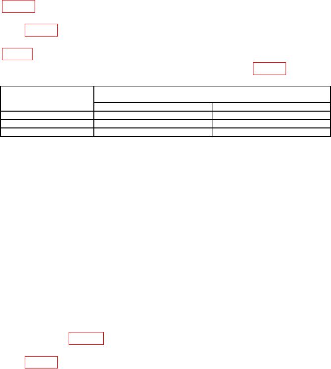
Table 28. Phase Modulation.
Measuring receiver phase modulation indications
Test instrument
(rad)
Carrier frequency
(MHz)
Min
Max
8
9
11
1050
9
11
0.50
9
11
(8) Press TI pushbuttons as listed in (a) through (j) below:
(a) FUNCTION-CARR FREQ.
(b) DATA ENTRY- 8 MHz.
(c) FUNCTION- CARR LEVEL.
(d) DATA ENTRY- 10 dBm.
(e) FUNCTION-MOD FREQ.
(f) DATA ENTRY- 1 kHz.
(g) FUNCTION-MOD LEVEL.
(h) DATA ENTRY- 10 RAD.
(i) MODULATION/AUX-MOD ON ONE (red light lit).
FUNCTION-RF ON to on (red light lit).
(j)
(9) Configure measuring receiver to measure 1 kHz PM modulation distortion.
(10) Using measuring receiver, measure PM modulation distortion. Measuring
receiver modulation distortion indication will be within limits specified for first carrier
frequency listed in table 29.
(11) Set TI FUNCTION-CARR FREQ and DATA ENTRY keys to next frequency
listed in table 29.
23

