
TB 9-6625-2331-24
(4) Set up the tunable active filter as a 50 kHz low pass filter.
(5) Set calibrator frequency and amplitude to first setting listed in table 5. TI should
indicate within the limits listed in table 5.
(6) Repeat (5) above for remaining settings listed in table 5.
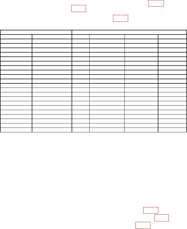
Table 5. Volt Max/Min.
Calibrator
Test instrument
Amplitude
Input
Function
Min
Max
-----------
-----------
A
VMin
-0.004
+0.004
DC
4.00 V
A
VMax
3.956
4.044
DC
4.00 V
A
VMin
3.956
4.044
1
DC
4.00 V
B
VMax
3.956
4.044
DC
4.00 V
B
VMin
3.956
4.044
DC
-4.00 V
B
VMax
-4.044
-3.956
DC
-4.00 V
B
VMin
-4.044
-3.956
1
DC
-4.00 V
A
VMax
-4.044
-3.956
DC
-4.00 V
A
VMin
-4.044
-3.956
2
DC
40.0 V
A
VMax
39.16
40.84
DC
40.0 V
A
VMin
39.16
40.84
DC
-40.0 V
A
VMax
-40.84
-39.16
DC
-40.0 V
A
VMin
-40.84
-39.16
1
DC
-40.0 V
B
VMax
-40.84
-39.16
DC
-40.0 V
B
VMin
-40.84
-39.16
DC
40.0 V
B
VMax
39.16
40.84
DC
40.0 V
B
VMin
39.16
40.84
3
100 kHz
1.414 V rms (4 V pp)
B
VMax/Min
3.756
4.244
1
100 kHz
1.414 V rms (4 V pp)
A
VMax/Min
3.756
4.244
100 kHz
6.372 V rms (18 V pp)
A
VMax/Min
16.16
19.84
100 kHz1
6.372 V rms (18 V pp)
B
VMax/Min
16.16
19.84
Press SWAP A↔B key.
1
Remove the tunable active filter from the connection.
2
3 Press MATH key, FUNCTION ◄ ►keys to select (K*X+L)/M, and ENTER.
b. Adjustments. No adjustments can be made.
11. Trig Level, A and B Outputs
a. Performance Check
(1) Connect the TI TRIG LEVEL A OUT (rear panel) to the multimeter inputs.
(2) Press TI keys as listed in (a) through (b) below:
(a) LOCAL/PRESET.
(b) TRIGGER LEVEL SET A.
(3) Press DATA ENTRY keys to set TI to first setting listed in table 6.
(4) Press ENTER and verify multimeter indicates within limits listed in table 6.
(5) Repeat steps (3) and (4) above for remaining settings in table 6.

