
TB 9-6625-2332-40
Trail and enter 1 from data keyboard and press n/GHz.
(e)
Per and enter 1 from data keyboard and press /MHz.
(f)
Duty and enter 50 from data keyboard and press ENTER/Hz.
(g)
DISABLE (model 9211 output module) to on (red light extinguished).
(h)
(4) Set digitizing oscilloscope channel 3 and trigger probe attenuation to 10.
(5) Setup digitizing oscilloscope to measure risetime.
(6) Verify that the digitizing oscilloscope indicates within the limits listed in table
10 for the Lead setting.
(7) Setup digitizing oscilloscope to measure falltime.
(8) Verify that the digitizing oscilloscope indicates within the limits listed in table
10 for the Trail setting.
(9) Set TI to the next Lead, Trail, and Per (if listed) settings listed in table 10.
(10) Repeat (5) through (8) above.
(11) Repeat (9) through (10) above for the remaining Lead, Trail, and Per settings
listed in table 10.
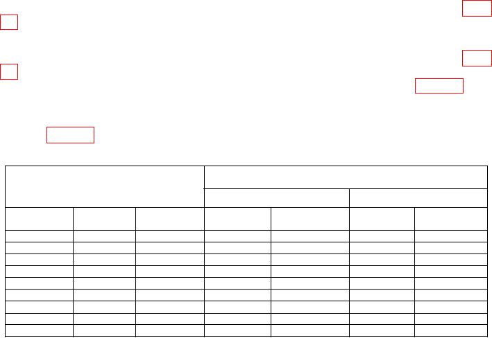
Table 10. 9211 Risetime and Falltime
Digitizing oscilloscope
indications (sec)
Test instrument
settings
Risetime
Falltime
Lead
Per setting
Trail setting
setting
Min
Max
Min
Max
sec
1 nsec
1
nsec
0.6 nsec
1.4 nsec
0.6 nsec
1.4 nsec
1
10 nsec
10
nsec
8.7 nsec
11.3 nsec
8.7 nsec
11.3 nsec
20 nsec
20
nsec
17.7 nsec
22.3 nsec
17.7 nsec
22.3 nsec
100 nsec
100
nsec
90 nsec
110
nsec
90
nsec
110
nsec
100 sec
sec
sec
0.9 sec
sec
sec
sec
1
1
1.1
0.9
1.1
sec
sec
sec
sec
sec
sec
10
10
9
11
9
11
sec
sec
sec
sec
sec
sec
10
msec
100
100
90
110
90
110
1 msec
1
msec
0.9 msec
1.1 msec
0.9 msec
1.1 msec
200
msec
10 msec
10
msec
9 msec
11
msec
9
msec
11
msec
(12) Press DISABLE pushbutton (model 9211 output module) to off (red light lit).
(13) Disconnect cable from TI 9211 module OUTPUT.
(14) Connect cable to TI 9215 module OUTPUT.
(15) Set digitizing oscilloscope channel 3 and trigger probe attenuation to 10.
(16) Press TI pushbuttons as listed in (a) through (h) below:
(a) CHANNEL B
(b) Vhigh and enter 5 from data keyboard and press ENTER/Hz.
(c) Vlow and enter 0 from the data keyboard and press ENTER/Hz.
(d) Lead and enter 6.5 from data keyboard and press n/GHz.
(e) Trail and enter 6.5 from data keyboard and press n/GHz.
12

