
TB 9-6625-2332-50
a. Performance Check
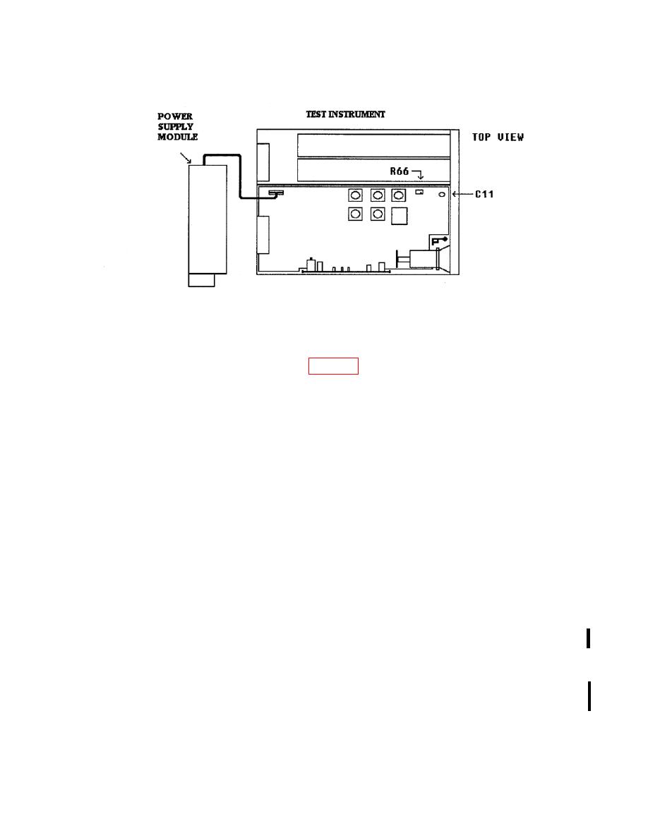
(1) Connect equipment as shown in figure 4 .
(2) Press TI pushbuttons as listed in (a) through (m) below:
(a)
CHANNEL A.
(b)
(c)
(d)
(e)
(f)
(g)
(h)
Double Off
(i)
Trigger Impedance 50.
(j)
Trigger Level 0.1.
(k)
Trigger Slope positive.
(l)
Trigger Mode single.
(m)
Press DISABLE pushbutton (model 9211 output module) to on (red light
extinguished).
(3) Set up function/arbitrary generator for an output of 1.02 Vpp 1.5 MHz square
wave.
(4) Set oscilloscope Vertical 1 and Vertical 2 input impedance to 50 Ω.
(5) Adjust oscilloscope controls to obtain a satisfactory dual two-channel display on
the crt.
(6) Verify for each positive pulse displayed on Vertical 1 of the oscilloscope that
there is one positive pulse displayed on Vertical 2.

