
TB 9-6625-2334-24
(3) Set signal generator for each frequency in table 11 and slowly increase signal
generator amplitude exceeds limits specified, perform b below.
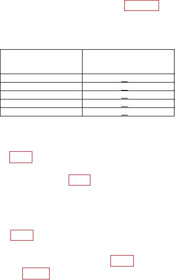
Table 11. Channel C Sensitivity
Signal generator
Adjusted signal
output
generator amplitude
(MHz)
(mV)
90
< 20
300
< 20
600
< 20
900
< 20
1300
< 20
b. Adjustments
(1) Set TI RESOLUTION, N switch to .1kHz.
(2) Adjust A8R12 (fig. 1) fully ccw.
(3) Set signal generator for a 1299 MHz, 100 mV output. Slowly decrease signal
generator amplitude while adjusting A8A1 (fig. 1) R22 for maximum sensitivity (at least 20 mV)
and a stable indication at approximately 1299 MHz (R).
(4) Set signal generator for a 90 MHz, 100 mV output. Slowly decrease signal
generator amplitude until TI displays erroneous indications above 100 MHz (Example:
101.nnnnn).
(5) Adjust A8R12 (fig. 1) until TI stops gating (R).
(6) Set signal generator for a 90 MHz, 125 mV output.
(7) Connect multimeter INPUT HI to A8A1 (fig. 1) pin 1 and LO to ground.
(8) Adjust A8A1 (fig. 1) R13 until
indication
switches
from
approximately 12 to 15 V dc to 10 V dc (R).
12. Digital Voltmeter (Option 021)
a. Performance Check
(1) Position controls as listed in (a) through (e) below:
FUNCTION switch to DVM.
(a)
FREQ RESOLUTION, N switch to 1Hz.
(b)
DCV RANGE switch to AUTO.
(c)
FILTER switch to OFF.
(d)
READ A and READ B pushbuttons out.
(e)
(2) Short TI HI and LO. If TI display does not indicate between -0.0004 V and
+0.0004 V, perform b (1) below.
(3) Disconnect short from TI HI and LO.
(4) Connect calibrator OUTPUT HI and LO to TI HI and LO.

