
TB 9-6625-2337-35
(3) Set the pulse generator to produce a 10 s wide, 5 V pulse with 0 s delay,
trigger mode to external, and slope to negative.
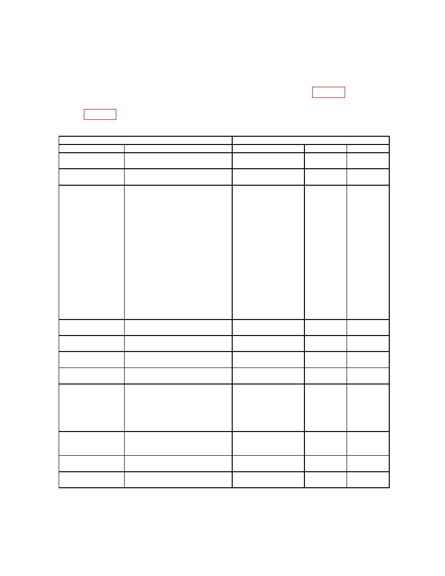
(4) Oscilloscope will indicate within limits listed in first row of table 34.
(5) Repeat technique of (2) through (4) above using remaining setting and limits
listed in table 34.
Table 34. KIR Characteristics
TI
Test description
Settings/connection
Measurement type
Minimum
Maximum
KIR EXT TRIG
--------------------------------------
Pulse count
28
28
channel 2
--------------------------
Set pulse generator for:
Pulse count
28
28
0.5 s width 1.5 V
channel 2
CHVID 4.5V LVL
Use the arrow keys to highlight
V Top
3.5 V
5.5 V
KIR TRIGGER:
Channel 2
ENTR (INT)
Press FUNC, ↑
2, ENTR (CHALLENGES)
Use the arrow keys to highlight
M4:
ENTR (SYNC)
Use the arrow keys to highlight
S2:
ENTR (OFF)
Use the arrow keys to highlight
S3:
ENTR (OFF)
Use the arrow keys to highlight
S4:
ENTR (OFF)
CHVID RISE
--------------------------------------
Rise Time
---------------
100 ns
TIME
channel 2
CHVID FALL
--------------------------------------
Fall Time
---------------
150 ns
TIME
channel 2
CHVID
--------------------------------------
Overshoot
---------------
5%
OVERSHOOT
channel 2
CHVID .5 S PW
--------------------------------------
Width
470 ns
530 ns
channel 2
167.5 s
CHVID 168 S
168.5 s
Disconnect Pulse Generator
Delta time channel 1
from setup. Connect TI
to channel 2
DLY
TRIGGERS M4 PRE OUT to
oscilloscope channel 1 input
using a 93 Ω feedthrough
termination.
GTC TRIG 4.5 V
Move connection from TI KIR
V Top
3.5 V
5.5 V
LVL
CH VID OUT to TI KIR GTC
Channel 2
TRIG OUT.
GTC TRIG RT
--------------------------------------
Rise Time
---------------
100 ns
Channel 2
GTC TRIG FT
--------------------------------------
Fall Time
---------------
200 ns
Channel 2
48

