
TB 9-6625-2337-35
(d)
Use the arrow keys to highlight M2:.
(e)
ENTR (ON).
(f)
Use the arrow keys to highlight REPLY SIGNAL:.
(g)
ENTR (SIF).
(h)
Use the arrow keys to highlight RF:.
(i)
0, ENTR (-0).
(j)
Use the arrow keys to highlight AUX:.
(k)
95, ENTR (-95).
Press FUNC, ↑.
(l)
(m)
11, ENTR (MAIN MODULATION).
(n)
Use the arrow keys to highlight GTC SHORT:.
(o)
ENTR (ON).
(4) Adjust the oscilloscope channel 1 and channel volts/div and vertical position
controls for 2 to 4 divisions of vertical deflection with the signal baseline on the center
graticule line (trigger oscilloscope on channel 1).
NOTE
The number of pulses displayed in the set on channel 2 will
vary depending on the TI settings.
(5) Adjust the oscilloscope horizontal Sec/Div and position control to display 2
pulses on channel 1 and 1 set of pulses on channel 2.
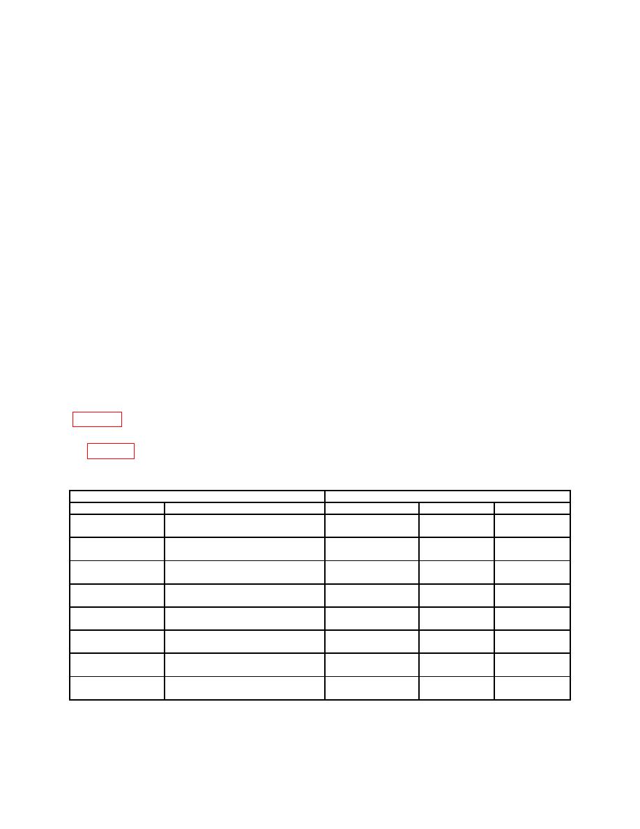
(6) Verify that the oscilloscope channel 2 indication is within limits listed in
(7) Repeat technique of 3 through (6) above for remaining settings and values listed
in table 39.
TI
Oscilloscope
Test description
Settings
Measurement type
Minimum
Maximum
GTC SHORT P1
----------------------------------------
Delta time from 2d
14.25 s
15.75 s
SPACE
to 3d pulse
GTC SHORT P2
----------------------------------------
Delta time from 2d
61.75 s
68.25 s
SPACE
to 4th pulse
GTC SHORT P3
----------------------------------------
Delta time from 2d
109.25 s
120.75 s
SPACE
to 5th pulse
GTC SHORT P4
----------------------------------------
Delta time from 2d
156.75 s
173.25 s
SPACE
to 6th pulse
GTC SHORT P1
----------------------------------------
Width pulse 3
400.0 ns
600.0 ns
PW
GTC SHORT P2
----------------------------------------
Width pulse 4
400.0 ns
600.0 ns
PW
GTC SHORT P3
----------------------------------------
Width pulse 5
400.0 ns
600.0 ns
PW
GTC SHORT P
----------------------------------------
Width pulse 6
400.0 ns
600.0 ns
PW
61

