
TB 9-6625-2339-24
17. Frequency Response
a. Performance Check
NOTE
If necessary, perform measuring receiver and sensor module
ZERO and CALIBRATE.
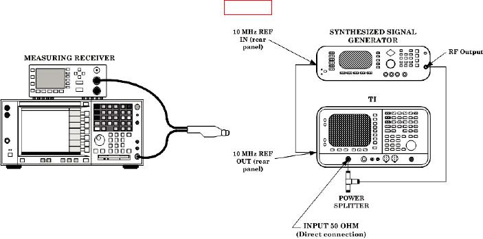
(1) Connect equipment as shown in figure 4.
Figure 4. Frequency response equipment setup.
(2) Connect measuring receiver power sensor input to the open end of the power splitter.
(3) Press TI keys as listed in (a) through (k) below:
(a)
Preset.
(b)
[Factory Preset] (if it is displayed).
(c)
System, [Alignments], [Auto Align], [Off].
(d)
Sweep, [Points 401].
(e)
FREQUENCY, 5, 0, [MHz].
(f)
SPAN, 2, 0, [kHz].
AMPLITUDE, [Ref Level], 5, [dBm].
(g)
(h)
[Attenuation], 1, 0, [dB] (Man).
(i)
[Scale/Div], 1, [dB].
(j)
BW/Avg, [Resolution BW], 3, [kHz] (Man).
(k)
[Video BW], 3, [kHz] (Man).
(4) Set synthesized signal generator frequency to 50 MHz and level output to -5 dBm.
(5) Configure measuring receiver to measure power in dBm at 50 MHz.
(6) Adjust synthesized signal generator power level for a measuring receiver
indication of -10 +/- 0.05 dBm.
(7) Press TI Single key.

