
TB 9-6625-2340-24
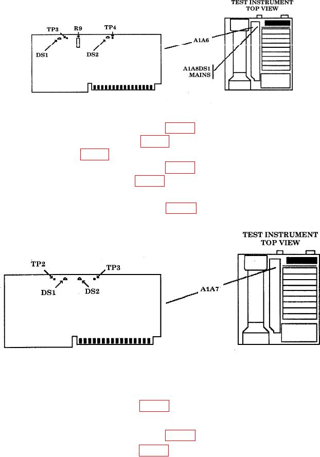
Figure 31. A1A6 board.
(5) Connect multimeter HI to A1A6TP3 (fig. 31) and multimeter LO to TI chassis.
(6) The +15 V indicator A1A6DS1 (fig. 31) (yellow LED) should be lit.
(7) Adjust A1A6R9 (fig. 31) for a multimeter indication of 15.000 0.010 V dc (R).
(8) Connect multimeter HI to A1A6TP4 (fig. 31) and multimeter LO to TI chassis.
(9) The 15V indicator A1A6DS2 (fig. 31) (yellow LED) should be lit.
(10) Multimeter should indicate 15.000 0.050 V dc.
(11) Connect multimeter HI to A1A7TP3 (fig. 32) and multimeter LO to TI chassis.
Figure 32. A1A7 Board
(12) The 120 V indicator A1A7DS1 (fig. 32) should be lit.
(13) Multimeter should indicate 120.0 2.0 Vdc.
(14) Connect multimeter HI to A1A7TP2 (fig. 32) and multimeter LO to TI chassis.
(15) The 5.2 V indicator A1A7DS1 (fig. 32) (yellow LED) should be lit.
(16) Multimeter should indicate 5.200 0.050 V dc.
80

