
TB 9-6625-2345-35
(d) SPAN/DIV, 5, 0, MHz +dBX.
(e) BLUE SHIFT.
(f) REF LEVEL, 0, kHz dBX.
(9) Set oscilloscope calibrator for a 20 ns MARKER output.
(10) Use TI CENTER/MARKER FREQUENCY knob to align markers on graticule
lines.
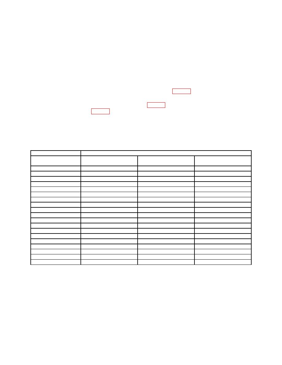
(11) Check alignment of markers to graticule lines over TI center eight divisions. If
alignment error is not within limits specified in first row of table 5, perform b below.
(12) Repeat technique of (8) (a) through (d) and (9) through (11) above for remaining
TI settings and oscilloscope calibrator outputs in table 5 below. If TI alignment is not
within limits specified in table 5, perform b below.
NOTE
Throughout this check use of TI REFERENCE LEVEL knob,
to adjust TI reference level, will be required to keep trace on
screen.
Oscilloscope calibrator
Test instrument
Marker alignment error
Marker output
Span/Div
(minor divisions)
20 ns
300 MHz
50 MHz
2
50 ns
100 MHz
20 MHz
2
100 ns
0 Hz
10 MHz
2
200 ns
0 Hz
5 MHz
2
500 ns
0 Hz
2 MHz
2
1 s
0 Hz
1 MHz
2
2 s
0 Hz
500 kHz
2
5 s
0 Hz
200 kHz
2
10 s
0 Hz
100 kHz
2
20 s
0 Hz
50 kHz
2
50 s
0 Hz
20 kHz
2
100 s
0 Hz
10 kHz
2
200 s
0 Hz
5 kHz
2
500 s
0 Hz
2 kHz
2
1 ms
0 Hz
1 kHz
2
2 ms
0 Hz
500 Hz
2
5 ms
0 Hz
200 Hz
2
10 ms
0 Hz
100 Hz
2
20 ms
0 Hz
50 Hz
2
(13) Reduce outputs to minimum and disconnect equipment setup.
b. Adjustments
(1) Press and release TI spectrum analyzer POWER key to OFF.
(2) Disconnect all connections made to TI spectrum analyzer.
12

