
TB 9-6625-2345-35
(14) Connect oscilloscope calibrator SOURCE/MEASURE CHAN 1 to TI RF
INPUT 50Ω.
(15) Press TI keys as listed in (a) through (d) below:
(a) BLUE SHIFT.
(b) FREQ, 5, 0, MHz +dBX.
(c) BLUE SHIFT.
(d) SPAN/DIV, 5, MHz +dBX.
(16) Set oscilloscope calibrator for a 200 ns MARKER output.
to TI second vertical graticule line.
(18) Adjust A1A48A1R1071 (fig. 3) for one marker per division over center eight
divisions of CRT (R).
(19) Press TI keys as listed in (a) through (d) below:
(a) BLUE SHIFT.
(b) FREQ, 2, 0, 0, kHz dBX.
(c) BLUE SHIFT.
(d) SPAN/DIV, 2, 0, kHz dBX.
to TI second vertical graticule line.
(21) Adjust A1A48A1R1067 (fig. 3) for one marker per division over center eight
divisions of CRT (R).
(22) Set oscilloscope calibrator to standby.
(23) Press TI BLUE SHIFT then RESET keys.
(24) Disconnect oscilloscope calibrator SOURCE/MEASURE CHAN 1 from TI RF
INPUT 50Ω.
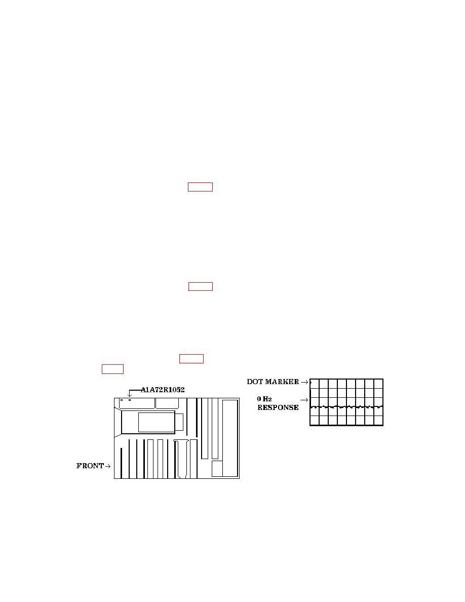
(25) Adjust A1A72R1052 (fig. 4) dot marker over 0 Hz response as shown in example
waveform in fig 4 (R).
Figure 4. 0 Hz adjustment.
14

