
TB 9-6625-2346-35
(a) VERTICAL MODE CH 1 BOTH CH 2 to CH 1.
(b) CH 1 and CH 2 VOLTS/DIV to 2m.
(c) A AND B SEC/DIV to .05 s.
(16) Set oscilloscope calibrator for a CHAN 1, EDGE mode output of 10 mV at a
frequency of 1 MHz.
(17) Adjust TI CH 1 ⇕ POSITION control to position top of displayed waveform to
center horizontal graticule line. If square wave aberrations are not within limits specified
in first row of table 5, perform b (83) through (91) below.
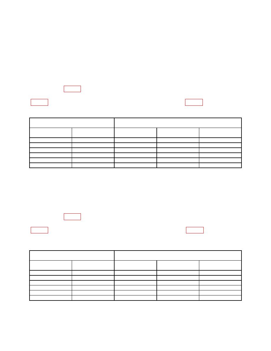
(18) Repeat technique of (15) (b), (16) and (17) above for settings and outputs listed in
through (91) below.
Oscilloscope calibrator
Test instrument
EDGE mode output
Amplitude
Frequency
A AND B SEC/DIV
VOLTS/DIV
Aberration limits
(s)
(minor divisions)
10
mVpp
1 MHz
0.05
2
mV
<1
50
mVpp
1 MHZ
0.05
10
mV
<1
100
mVpp
1 MHz
0.05
20
mV
<1
250
mVpp
1 MHz
0.05
50
mV
<1
.5 Vpp
1 MHz
0.05
.1 V
<1
1 Vpp
1 MHz
0.05
.2 V
<1
(19) Set oscilloscope calibrator output to standby.
(20) Set TI VERTICAL MODE CH 1 BOTH CH 2 switch to CH 2.
(21) Set oscilloscope calibrator for a CHAN 2, EDGE mode output of 10 mV at a
frequency of 1 MHz.
(22) Adjust TI CH 1 ⇕ POSITION control to position top of displayed waveform to
center horizontal graticule line. If square wave aberrations are not within limits specified
in first row of table 6, perform b (92) through (100) below.
(23) Repeat technique of (15) (b), (16) and (17) above for settings and outputs listed in
through (100) below.
Oscilloscope calibrator
Test instrument
EDGE mode output
Amplitude
Frequency
A AND B SEC/DIV
VOLTS/DIV
Aberration limits
(s)
(minor divisions)
10
mVpp
1 MHz
0.05
2 mV
<1
50
mVpp
1 MHZ
0.05
10 mV
<1
100
mVpp
1 MHz
0.05
20 mV
<1
250
mVpp
1 MHz
0.05
50 mV
<1
.5 Vpp
1 MHz
0.05
.1 V
<1
1 Vpp
1 MHz
0.05
.2 V
<1
8

