
TB 9-6625-2346-35
(52) Position controls as listed in (a) through (d) below:
(a) VERTICAL MODE CH1 BOTH CH2 switch to CH 1.
(b) HORIZONTAL MODE A ALT B switch to A.
(c) A TRIGGER NORM pushbutton pressed.
(d) A TRIGGER A SOURCE switch to EXT.
(53) Connect oscilloscope calibrator SOURCE/MEASURE CHAN 1 to TI EXT
INPUT using a 50Ω feed through termination.
(54) Set oscilloscope calibrator for a SOURCE/MEASURE CHAN 1, LEVEL SINE
output of 10 MHz at an amplitude of 35 mV.
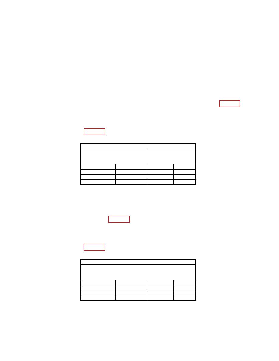
(55) Set TI A TRIGGER pushbuttons to combination listed in first row of table 21.
(56) Press in and hold TI TRIG VIEW pushbutton while adjusting A TRIGGER
LEVEL control to obtain a stable display.
(57) Repeat technique of (55) and (56) above for remaining A TRIGGER pushbutton
combinations listed in table 21.
Test instrument
A TRIGGER pushbutton
A TRIGGER LEVEL
with TRIG VIEW in
stable display
MODE
SLOPE
YES
NO
NORM
IN:
P-P AUTO
IN:
P-P AUTO
OUT:
(58) Release TRIG VIEW pushbutton.
(59) Set oscilloscope calibrator for a SOURCE/MEASURE CHAN 1, LEVEL SINE
output of 60 MHz at an amplitude of 120 mV.
(60) Pull X10 CAL control to out position and set TI A TRIGGER pushbuttons to
combination listed in first row of table 22.
(61) Press in and hold TI TRIG VIEW pushbutton while adjusting A TRIGGER
LEVEL control to obtain a stable display.
(62) Repeat technique of (60) and (61) above for remaining A TRIGGER pushbutton
combinations listed in table 22.
Test instrument
A TRIGGER pushbutton
A TRIGGER LEVEL
with TRIG VIEW in
stable display
MODE
SLOPE
YES
NO
NORM
IN:
P-P AUTO
IN:
P-P AUTO
OUT:
(63) Release TRIG VIEW pushbutton.
26

