
TB 9-6625-2346-35
(64) Set oscilloscope calibrator for a SOURCE/MEASURE CHAN 1, LEVEL SINE
output of 100 MHz at an amplitude of 150 mV.
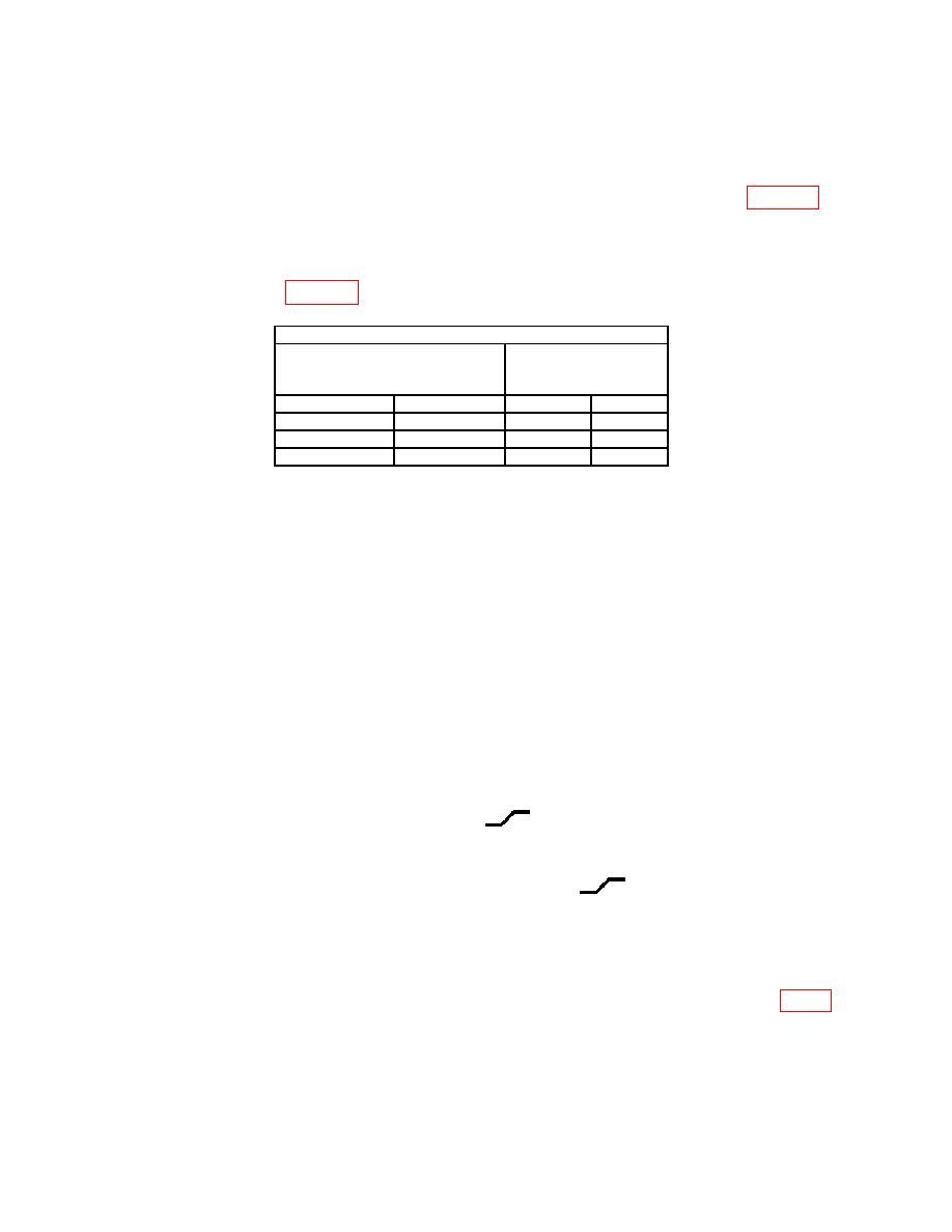
(65) Set TI A TRIGGER pushbuttons to combination listed in first row of table 23.
(66) Press in and hold TI TRIG VIEW pushbutton while adjusting A TRIGGER
LEVEL control to obtain a stable display.
(67) Repeat technique of (60) and (61) above for remaining A TRIGGER pushbutton
combinations listed in table 23.
Test instrument
A TRIGGER pushbutton
A TRIGGER LEVEL
with TRIG VIEW in
stable display
MODE
SLOPE
YES
NO
NORM
IN:
P-P AUTO
IN:
P-P AUTO
OUT:
b. Adjustments
NOTE
For adjustment of model 2236, perform steps (1) through (27)
below. For adjustment of model 2236A, perform only steps (10)
through (27) below.
(1) Disconnect equipment setup.
(2) Position TI controls as listed in (a) through (m) below:
(a)
All POSITION controls to midrange.
(b)
VERTICAL MODE CH 1 BOTH CH 2 switch to BOTH.
(c)
VERTICAL MODE ADD ALT CHOP switch to ALT.
(d)
CH 1 and CH 2 VOLTS/DIV switches to .5.
(e)
CH 1 and CH 2 AC GND DC switches to GND.
(f)
HORIZONTAL MODE A ALT B switch to A.
(g)
A AND B SEC/DIV switches to 1 ms.
(h) B TRIGGER SLOPE to OUT:
.
(i) B TRIGGER LEVEL to midrange.
(j) A TRIGGER P-P AUTO pushbutton pressed.
(k) A TRIGGER SLOPE pushbutton to OUT:
.
(l) A TRIGGER LEVEL to midrange.
(m) A TRIGGER A&B INT switch to CH 2.
(3) Adjust TI CH 1 and CH 2 ⇕POSITION controls to set both traces to the center
horizontal graticule line.
(4) Connect digital multimeter LO to chassis ground and HI to TP460 (fig. 1).
Digital multimeter indication will be less than 80 mV dc. Record digital multimeter
indication.
(5) Set TI A TRIGGER A&B INT switch to CH 1.
27

