
TB 9-6625-2347-35
(14) Set TI SEC/DIV to .1 s.
(15) Ensure oscilloscope calibrator is set for a CHAN 1, MARKER mode output
of 10 ns/div.
(16) Adjust TI TRIGGER LEVEL, INTENSITY, and CH 1 ⇕POSITION controls
for suitable viewing.
(17) Adjust TI ⇦POSITION⇨ control to align 1st time marker that is 50 ns beyond
start of sweep with 2nd vertical graticule line.
(18) Rotate oscilloscope calibrator knob located below EDIT FIELD pushbutton to
and TI linearity are not within limits specified in first row table 9, perform b below.
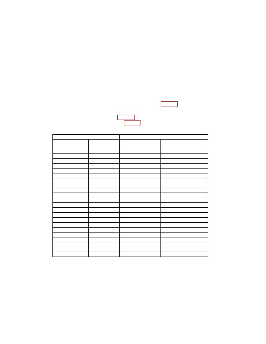
(19) Repeat technique of (14) through (18) above for remaining TI settings and
oscilloscope calibrator outputs listed in table 9. If oscilloscope calibrator err display and TI
linearity are not within limits specified in table 9, perform b below.
Oscilloscope calibrator
Test instrument
MARKER
Err display
SEC/DIV
Linearity over any 2 of
output
limit
setting
center 8 divisions
(div)
(%)
.1 s
≤ 0.4
10 nS/D
5
20 nS/D
.2 s
≤ 0.4
5
50 nS/D
.5 s
≤ 0.4
5
.1 S/D
1
s
≤ 0.4
5
.2 S/D
2
s
≤ 0.4
5
.5 S/D
5
s
≤ 0.4
5
1 S/D
10
s
≤ 0.4
5
2 S/D
20
s
≤ 0.4
5
5 S/D
50
s
≤ 0.4
5
10 S/D
.1 ms
≤ 0.4
5
20 S/D
.2 ms
≤ 0.4
5
50 S/D
.5 ms
≤ 0.4
5
.1 mS/D
1
ms
≤ 0.4
5
.2 mS/D
2
ms
≤ 0.4
5
.5 mS/D
5
ms
≤ 0.4
5
1 mS/D
10
ms
≤ 0.4
5
2 mS/D
20
ms
≤ 0.4
5
5 mS/D
50
ms
≤ 0.4
5
≤ 0.4
10 mS/D
5
.1 sec
≤ 0.4
20 mS/D
5
.2 sec
≤ 0.4
50 mS/D
5
.5 sec
(20) Position TI controls as listed in (a) through (d) below:
(a)
CH 1 VOLTS/DIV switch to .5.
(b)
SEC/DIV variable knob pushed in.
(c)
SEC/DIV to .2 ms.
(d)
SEC/DIV variable knob to fully ccw.
15

