
TB 9-6625-2347-35
(21) Set oscilloscope calibrator is for a CHAN 1 , MARKER mode output of
0.5 ms/div.
(22) Adjust TRIGGER LEVEL, INTENSITY, and CH 1 ⇕POSITION controls for
suitable viewing.
(23) Adjust TI ⇦POSITION⇨ control to align 2nd time marker with 2nd vertical
graticule line.
(24) Displayed markers will be ≤ 1 division apart.
(25) Rotate TI SEC/DIV variable knob to fully cw detent position.
(26) Set oscilloscope calibrator output to minimum and disconnect equipment setup.
(27) Position TI controls as listed in (a) through (g) below:
(a) CH1 AC GND DC switch to GND.
(b) HORIZONTAL MODE NO DLY INTENS DLY'D switch to INTENS.
(c) DELAY TIME MULTIPLIER knob fully ccw to < X1.
(d) DELAY TIME .02 ms 10 s 0.5 s switch to 0.5 s.
(e) SEC/DIV to .1 s.
(f) TRIGGER SOURCE switch to INT.
(g) TRIGGER MODE switch to AUTO.
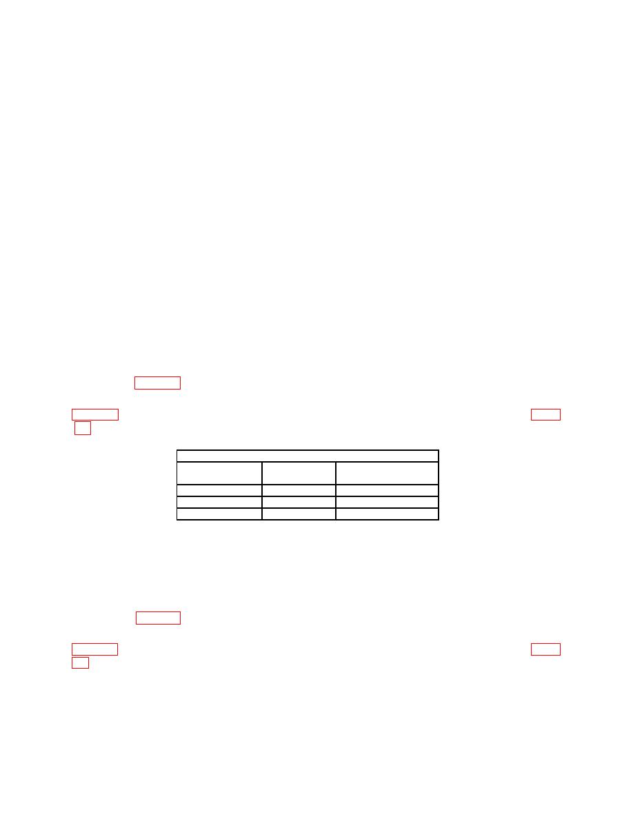
(28) Nonintensified portion of TI displayed trace will be within limits specified in
first row of table 10.
(29) Repeat technique of (27) (d) and (27) (e) above for remaining TI settings listed in
Test instrument
DELAY TIME
SEC/DIV
Nonintensified limit
setting
setting
(divisions)
0.5 s
.1 s
<5
10 s
2 s
<5
50 s
<4
0.2 ms
(30) Position TI controls as listed in (a) through (c) below:
(a) DELAY TIME MULTIPLIER knob fully cw to > X20.
(b) DELAY TIME .02 ms 10 s 0.5 s switch to 0.5 s.
(c) SEC/DIV to 2 s.
(31) Nonintensified portion of TI displayed trace will be within limits specified in
first row of table 11.
(32) Repeat technique of (30) (b) and (30) (c) above for remaining TI settings listed in
16

