
TB 9-6625-2347-35
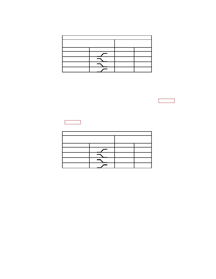
Test instrument
TRIGGER switch
TRIGGER LEVEL
stable display
MODE
SLOPE
YES
NO
AUTO
AUTO
NORM
NORM
(19) Set TI VERTICAL MODE CH1 BOTH CH2 switch to CH 1.
(20) Set oscilloscope calibrator to STANDBY and move connection to TI CH 1 OR X
input.
(21) Set oscilloscope calibrator to OPERATE.
(22) Set TI TRIGGER switches to combination listed in first row of table 15.
(23) Adjust TI TRIGGER LEVEL control to obtain a stable display. If a stable
display cannot be obtained perform b below.
(24) Repeat technique of (22) and (23) above for remaining TRIGGER pushbutton
combinations listed in table 15. If a stable display cannot be obtained perform b below.
Test instrument
TRIGGER switch
TRIGGER LEVEL
stable display
MODE
SLOPE
YES
NO
NORM
NORM
AUTO
AUTO
(25) Reduce oscilloscope calibrator output to minimum and disconnect equipment
setup.
(26) Position TI switches as listed in (a) through (d) below:
(a) Ensure VERTICAL MODE CH1 BOTH CH2 is set to CH 1.
(b) CH 1 VOLTS/DIV to 10 m.
(c) CH 2 VOLTS/DIV to 10 m.
(d) SEC/DIV to 20 s.
(27) Connect oscilloscope calibrator SOURCE/MEASURE CHAN 1 to dual input
cable.
(28) Connect one open end of dual input cable using 10X attenuator and 50 Ω
feedthrough termination to TI CH 1 OR X input.
(29) Connect other end of dual input cable using 10X probe supplied with TI to TI
CH 2 OR Y input.
21

