
TB 9-6625-2347-35
(30) Set oscilloscope calibrator for a CHAN 1, LEVEL SINE output of 50 kHz and 5
divisions of vertical display on TI.
(31) Position TI controls as listed in (a) through (c) below:
(a) VERTICAL MODE CH1 BOTH CH2 switch to CH 2.
(b) SEC/DIV switches to .2 s.
(c) TRIGGER SOURCE switch to EXT.
(32) Move connection from TI CH 1 OR X input to TI EXT INPUT.
(33) Rotate oscilloscope calibrator knob below EDIT FIELD pushbutton to increase
oscilloscope calibrator frequency to 2 MHz.
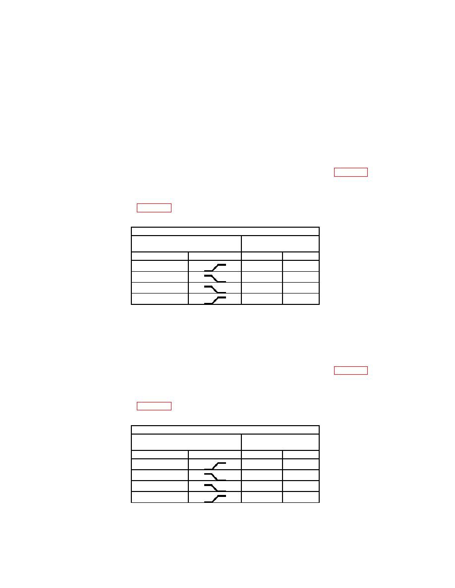
(34) Set TI TRIGGER switches to combination listed in first row of table 16.
(35) Adjust TI TRIGGER LEVEL control to obtain a stable display.
(36) Repeat technique of (34) and (35) above for remaining TRIGGER pushbutton
combinations listed in table 16.
Test instrument
TRIGGER switch
TRIGGER LEVEL
stable display
MODE
SLOPE
YES
NO
AUTO
AUTO
NORM
NORM
(37) Set oscilloscope calibrator to STANDBY and remove 10X attenuator from
connection.
(38) Set TI TRIGGER EXT COUPLING AC DC DC10 switch to DC10.
(39) Set oscilloscope calibrator to OPERATE.
(40) Set TI TRIGGER switches to combination listed in first row of table 17.
(41) Adjust TI TRIGGER LEVEL control to obtain a stable display.
(42) Repeat technique of (40) and (41) above for remaining TRIGGER pushbutton
combinations listed in table 17.
Test instrument
TRIGGER switch
TRIGGER LEVEL
stable display
MODE
SLOPE
YES
NO
NORM
NORM
AUTO
AUTO
22

