
TB 9-6625-2347-35
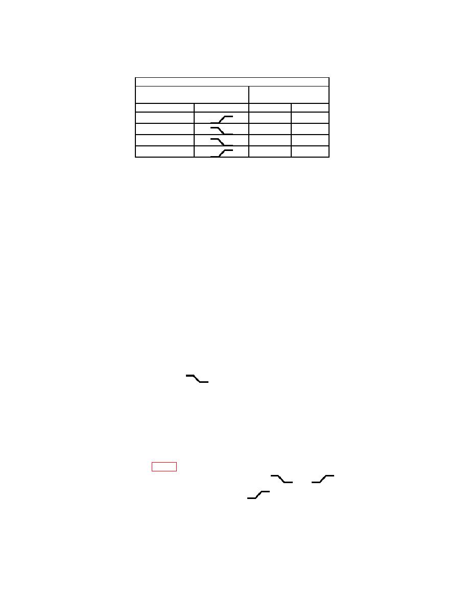
Test instrument
TRIGGER switch
TRIGGER LEVEL
stable display
MODE
SLOPE
YES
NO
NORM
NORM
AUTO
AUTO
(58) Reduce oscilloscope calibrator output to minimum and disconnect equipment
setup.
b. Adjustments
(1) Disconnect equipment setup.
(2) Position TI controls as listed in (a) through (p) below:
CH 1 ⇕ POSITION to midrange.
(a)
(b)
VERTICAL MODE CH 1 BOTH CH 2 to CH 1.
(c)
CH 1 and CH 2 VOLTS/DIV switches to 20 m.
(d)
CH 1 and CH 2 VOLTS/DIV CAL fully cw to detent.
(e)
CH 2 INVERT pushbutton to out position.
(f)
CH 1 and CH 2 AC GND DC switches to DC.
⇦POSITION⇨ to midrange.
(g)
(h)
HORIZONTAL MODE switch to NO DLY.
(i)
SEC/DIV switch to 20 s.
(j)
SEC/DIV variable fully cw to detent and pushed in.
(k)
VAR HOLDOFF fully ccw to NORM.
(l)
TRIGGER MODE AUTO NORM TV FIELD switch to AUTO.
(m) SLOPE switch to
.
(n) INT switch to VERT MODE.
(o) SOURCE switch to INT.
(p) EXT COUPLING switch to DC.
(3) Connect oscilloscope calibrator SOURCE/MEASURE CHAN 1 to TI CH 1 OR
X input using a 50 Ω feedthrough termination.
(4) Set oscilloscope calibrator for a CHAN 1, LEVEL SINE output of 50 kHz and 5
divisions of TI vertical display.
(5) Adjust R482 (fig. 1) for a positive vertical shift of 0.15 division at sweep start
and
positions (R).
when changing TI TRIGGER SLOPE switch between
(6) Set TI TRIGGER SLOPE switch to
and TI TRIGGER LEVEL knob to
fully cw position.
(7) Adjust oscilloscope calibrator output amplitude for 1 division of TI vertical
display.
24

