
TB 9-6625-2354-35
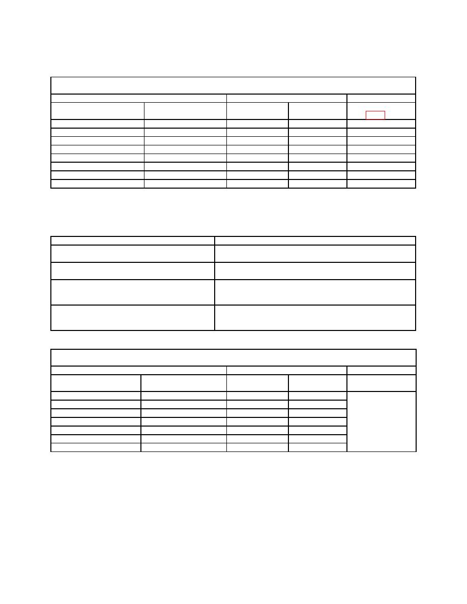
Table 11e. Simpson, Model 260-7M Dc Current
Calibration Performance Limits and Adjustments
Dc Current
Test instrument
Calibrator
Test instrument
1
Indication
Initial output
err indication
Adjustments
Dc current range
(A)
(A)
(%)
(fig. 2) (R)
50 A2
50 A
50 A
1.5
R1
1 mA
1 mA
1 mA
2
R2
10 mA
10 mA
10 mA
2
----
10 mA
6 mA
6 mA
3.3
----
10 mA
2 mA
2 mA
10
----
100 mA
100 mA
100 mA
2
----
500 mA
500 mA
500 mA
2
----
10 A
10 A
10 A
2
----
3
TI must be calibrated in horizontal position.
1
Connect positive lead to TI +50A/250mV input. After 50 A check is complete, reduce output to minimum and move
2
positive lead to TI + input.
3 Reduce output to minimum and connect TI negative lead to -10A input and connect TI positive lead to +10A input.
Table 12a. Simpson, Model 260-7P Specifications
Test instrument parameter
Performance specification
Dc voltage
Range: 0 to 1000 V
2% of FS
Accuracy:
Ac voltage
Range: 0 to 1000 V
3% of FS
Accuracy:
Range: 0 to 20 MΩ
2.5 of arc for RX1 range, 2 of arc for
Accuracy:
all other ranges
Dc current
Range: 0 to 10A
1.5% of FS for 50 A range, 2% of FS for
Accuracy:
all other ranges
Table 12b. Simpson, Model 260-7P Dc Voltage
Calibration Performance Limits and Adjustments
Dc Voltage
Test instrument
Calibrator
Test instrument
1
Indication
Initial output
err indication
Dc volts range
(V)
(V)
(%)
Adjustments
1
1
1
2
2
2.5
2.5
2.5
2
10
10
10
2
50
50
50
2
None
250
250
250
2
500
500
500
2
1000
1000
1000
2
3
TI must be calibrated in horizontal position.
1
Connect positive lead to TI +1V DC input. After 1V check is complete, reduce output to minimum and move positive lead to
2
TI + input.
3 Reduce output to minimum and move positive lead from TI + input to TI 1000V DC/AC input. After 1000V check is
complete, reduce output to minimum and move positive lead to TI + input.
21

