
TM 9-6625-2802-35
(6) Set INPUT switch to OPR. Pen should
8 transformer for a 30 volt (peak-to-peak)
track grid line 15 millimeters right of center
output as observed on oscilloscope.
line, + 0.5 mm.
(5) Connect cable assembly (B2) to the
(7) Repeat steps (1) through (6) above for
preamplifier output CHANNEL OUT 1 of
channel 2.
terminal block on the back so as to
monitor an amplitude null on oscilloscope.
b. Adjustments.
If a null is not evident, perform
adjustments in paragraph 9 b.
(1) Turn LINE switch to OFF and remove dc
voltage standard.
(6) Repeat steps (1) through (5) above for
channel 2.
(2) Remove top right cover, slide preamplifier
out of chassis, remove its cover and
b. Adjustments.
reinsert it into the chassis.
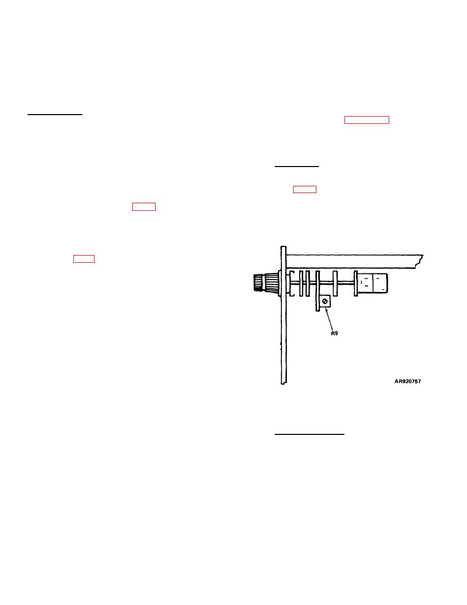
(1) Adjust resistor R9 on range switch (see
(3) Connect cable assembly (B2) from the
on oscilloscope at CHANNEL OUT 1
digital voltmeter (A2) to TP1 on the
terminal block (rear panel).
preamplifier (see fig. 2).
(2) Disconnect variable power transformer
(4) Set LINE switch to ON and INPUT switch
(A8).
to ZERO.
(5) Adjust PREAMP BAL resistor (R13) (see
9. Attenuator Balance.
a. Performance Check.
(1) Set up preamplifier INPUT switch to OPR
and range switch to .5V/DIV.
(2) Use adapter (B1) to connect cable
assembly (B2) to oscilloscope (A4).
(3) Connect variable power transformer (A8)
to isolation power transformer (A3);
connect isolation power transformer (A3)
through power cable (B4) to the
preamplifier input.
Figure 3. Range switch assembly 10. Dc Calibration.
(4) Use cable assembly (B2) to monitor the ac
10. Dc Calibration
output from variable power transformer on
a. Performance Check.
oscilloscope;
set
variable
power
(1) Use cable (B3) to connect dc voltage
standard (Al) to the channel preamplifier
input.
8

