
TB 9-6625-336-35
(2) Vary autotransformer (A1) output from 105 to 125 and back to 115 V ac while
observing frequency counter. If frequency counter indication does not remain between
99.500 and 100.500 MHz, perform b below.
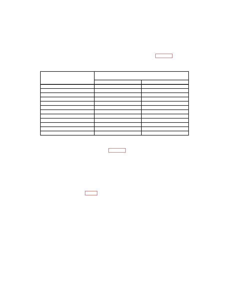
(3) Set FREQUENCY MEGACYCLES dial as listed in table 4. If frequency
counter does not indicate within limits specified, perform b below.
Table 4. Oscillator Frequency
Test instrument
Frequency counter indications (MHz)
FREQUENCY
Min
Max
MEGACYCLES dial settings
110
109.45
110.55
120
119.40
120.60
130
129.35
130.65
140
139.30
140.70
1501
149.25
150.75
160
159.20
160.80
170
169.15
170.85
180
179.10
180.90
190
189.05
190.95
200
199.00
201.00
210
208.95
211.05
2202
218.90
221.10
1Monitor
frequency counter for a period of 60 seconds. Frequency counter will not change by more than 3 kHz.
Not on all models.
2
(4) Connect equipment as shown in figure 1, connection B.
(5) Rotate FREQUENCY MEGACYCLES dial throughout frequency range.
Multimeter (A4) will indicate at least 2 V at its maximum voltage indication.
b. Adjustments
(1) Set FREQUENCY MEGACYCLES dial to 200.
(2) Adjust C3 and C28 (fig. 2) for a 200-MHz indication on frequency counter (R).
NOTE
It may be necessary to adjust C3 and C28 for best compromise
over entire frequency range.
a. Performance Check
(1) Connect oscilloscope calibrator (A6) FAST RISE + OUTPUT to oscilloscope (A5)
vertical input, using two cables (B5) and variable attenuator (A8).
6

