
TB 9-6625-357-35
(5) Repeat technique of (1) through (4) above for selector switch, frequency dial, and
function/arbitrary generator frequencies listed in table 6.
(6) Repeat technique of (1) through (5) above for INPUT 2.
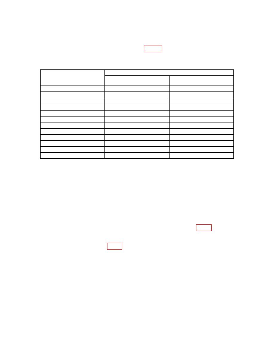
Table 6. Distortion
Test instrument
Function/arbitrary generator
frequency
Frequency dial settings
Selector switch settings
(Hz)
50
20
LOW PASS X10
120
20
LOW PASS X100
300
20
LOW PASS X100
1000
20
LOW PASS X100
10,000
20
LOW PASS X1K
20,000
20
LOW PASS X10K
70
2
HIGH PASS X10
120
2
HIGH PASS X10
700
2
HIGH PASS X100
1000
2
HIGH PASS X100
10,000
2
HIGH PASS X1K
70,000
2
HIGH PASS X10K
b. Adjustments. No adjustments can be made.
12. Power Supply
NOTE
Do not perform power supply checks if all other parameters are
within tolerance.
Power supply adjustments affect both
sections of the TI. If adjustments are made during checkout of
right section, calibration of left section must be repeated.
ground. If multimeter does not indicate between 240 and 360 V dc, perform b below.

