
TB 9-6625-396-50
b. Adjustments
(1) Remove TI protective cover.
(2) Repeat a(3) above.
(3) Set RANGE switch to d position.
(4) Repeat a(5) and (6) above.
(5) Set L switches to value indicated on calibration certificate for 100 mH inductor
plus value recorded in a(7) above.
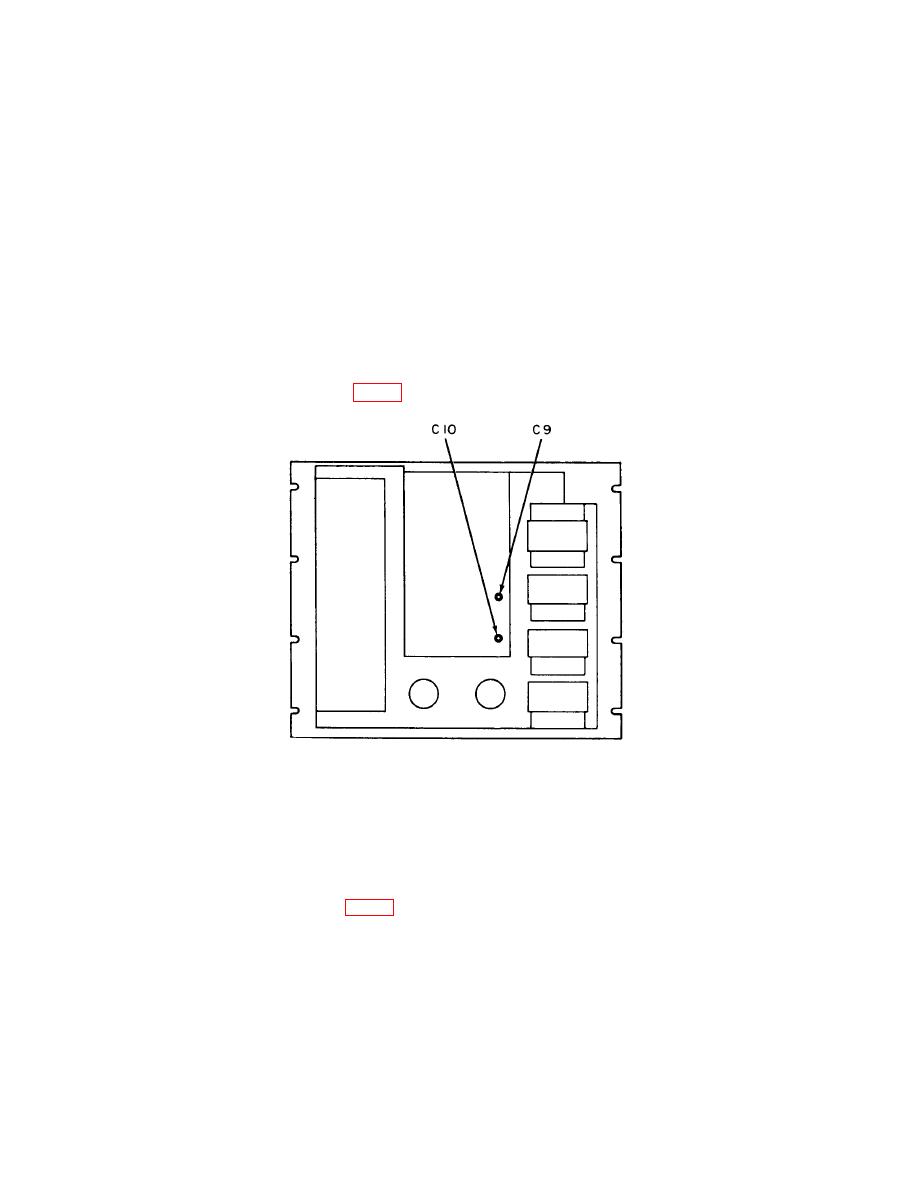
(6) Adjust capacitor C10 (fig. 2) for minimum indication on null detector (R).
Figure 2. Inductance bridge - rear,.
(7) Set MAXIMUM SENSITIVITY switch to HIGH-Z position.
(8) Adjust L and G switches for a null on null detector.
(9) Repeat (5) above.
(10) Adjust capacitor C9 (fig. 2) for minimum indication on null detector (R).
(11) Replace protective cover.
(12) Set MAXIMUM SENSITIVITY switch to LOW-Z.
7

