
TB 9-6625-967-35
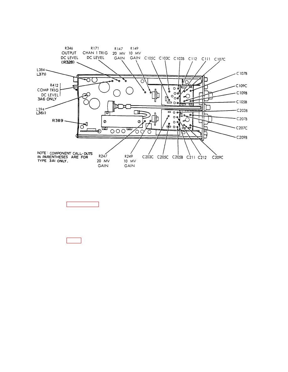
Figure 1. Dual-trace amplifier-left interior view
NOTE
Interaction exists between CHAN 1 TRIG DC LEVEL R171
and CH1 and DC BAL.
If R171 was adjusted, repeat
paragraph 7e above.
(3) Push in TI TRIGGER (CHI ONLY PULL) switch.
(4) Position and maintain trace on horizontal graticule centerline on oscilloscope crt.
If ac/dc voltmeter does not indicate between -0.4 and +0.4 volt dc, adjust COMP TRIG DC
LEVEL R412 (fig. 1) to obtain required indication on ac/dc voltmeter for type 3A6 only.
b. Adjustments. No further adjustments can be made.
10. Amplifier Gain (10 mV)
a. Performance Check
(1) Connect ac calibrator (A1) to TI CH1 and CH2 inputs, using two cables (B5).
(2) Turn TI CALIB (front panel screwdriver control) to midrange and set CH1 and
CH2 AC-DC-GND switches to AC.
7

