
TB 9-6685-327-35
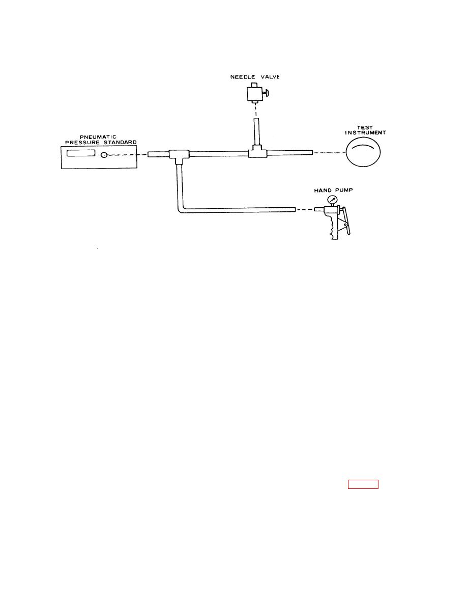
Figure 1. Pressure or vacuum - equipment setup.
NOTE
Insure that pneumatic pressure standard 0 to 120 inches of
water transducer has been zeroed within the last 8 hours.
(3) Connect BNC cable from INCHES H20 Output connector on rear of pneumatic
pressure standard to EXT INPUT connector on front panel of pneumatic pressure standard.
(4) Position controls on pneumatic pressure standard as listed in (a) through (e)
below:
(a) POWER switch to ON.
(b) SOURCE pushbuttons to EXT.
(c) UNITS DISPLAYED switch to INCHES H20.
(d) SENSITIVITY pushbutton to HIGH.
(e) RESET pushbutton pressed.
(5) Calculate tolerance for TI being calibrated from specifications in table 1.
(6) Operate hand pump and needle valve (vent) until TI pointer indicates at the last
major division (cardinal point ) on scale. If pneumatic pressure standard does not indicate
4

