
TB 9-6695-261-35
b. Adjustments
(1) Connect oscilloscope to test point AO (fig. 1) located on PC418 card using probe.
(2) Position FREQUENCY Hz pushbuttons to indicate 1-0-0 and press
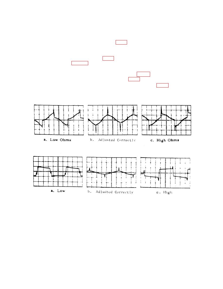
MULTIPLIER 1 pushbutton. If square wave component in the signal present at test point
AO is not less than 10 mV, adjust P331 (fig. 1) for minimum signal (R). Typical oscilloscope
presentation is shown in figure 2.
(3) Position FREQUENCY Hz pushbuttons to indicate 0-9-0 and press
test point AO is not less than 100 mV p-p, adjust P421 (fig. 1) for minimum signal (R).
(4) Press MULTIPLIER 10 pushbutton, and adjust R142B (fig. 1) for a 0 V dc
output level (R).
10. Attenuation
a. Performance Check
(2) Turn RMS VOLTS vernier control fully ccw.
(3) Press FREQUENCY Hz pushbuttons to indicate 1-0-0 and press
9.182 V rms, perform b below.

