
TB 9-6695-261-35
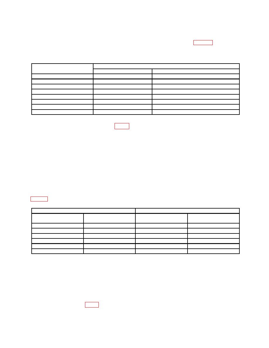
(4) Set RMS VOLTS switch and control to settings listed in table 5. True rms
voltmeter will indicate within limits specified.
Table 5. Attenuation
Test instrument RMS VOLTS
True rms voltmeter indication (V rms)
switch and control settings
Min
Max
8-9
7.838
8.162
7-8
6.858
7.142
6-7
5.878
6.122
5-6
4.898
5.102
4-5
3.918
4.082
3-4
2.938
3.062
2-3
1.958
2.042
1-2
0.978
1.022
11. Frequency Response
a. Performance Check
(2) Position controls as listed in (a) through (c) below:
(a) FREQUENCY Hz pushbuttons to indicate 1-0-0.
(b) MULTIPLIER 10 pushbutton pressed.
(c) RMS VOLTS switch to 9-10 and vernier control for a 9-V indication on
differential voltmeter.
(3) Position FREQUENCY Hz and MULTIPLIER pushbuttons as indicated in
Table 6. Frequency Response
Test instrument
Differential voltmeter indication (V)
FREQUENCY Hz
MULTIPLIER
Min
Max
pushbuttons
pushbuttons
1-0-0
.1
8.973
9.027
1-0-0
1
8.9775
9.0225
1-0-0
100
8.9775
9.0225
1-0-01
10
9.00
9.00
1-0-0
1000
8.82
9.18
9-9-9
1000
8.82
9.18
1Substitute
true RMS voltmeter for differential voltmeter. Adjust RMS VOLTS vernier for a 9 V reference.
b. Adjustments
(1) Connect ∼ OUTPUT to true rms voltmeter.
(2) Set RMS VOLTS vernier control fully ccw.
(3) Press FREQUENCY
Hz
pushbuttons
to
indicate
9-9-9
and
press
MULTIPLIER 1000 pushbutton.
(4) Adjust C132 (fig. 1) until true rms voltmeter indicates 9.00 V (R).

