
TB 9-6695-294-35
(11) AVG to off.
(12) ZERO to on.
b. Press EXT GD IN pushbutton to in.
c. Allow at least 2 hours for TI to warm up and stabilize.
8. Dc Voltage
a. Performance Check
(1) Connect calibrator OUTPUT HI, LO and V-GUARD to TI VOLTS INPUT/OHMS
SENSE HI, LO and GD.
(2) Press TI RANGE ↑ or ↓ pushbutton to select the 100 mV range.
(3) Set calibrator for a 100 mV dc output. If TI does not indicate between 99.995 (-3) and
100.005 (-3), perform b below.
(4) Repeat technique of (2) and (3) above using settings listed in table 3. If TI does not
indicate within limits specified, perform b below.
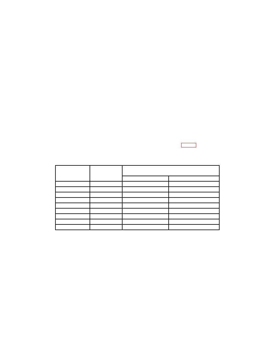
Table 3. Dc Voltage
Test
Calibrator
Test instrument
instrument
output
indications
range settings
settings
Min
Max
100 mV
-100 mV
-99.995 (-3)
-100.005 (-3)
1V
1V
0.99995
1.00005
1V
-1 V
-0.99995
-1.00005
10 V
10 V
9.9995
10.0005
10 V
-10 V
-9.9995
-10.0005
100 V
100 V
99.995
100.005
100 V
-100 V
-99.995
-100.005
1000 V
1000 V
999.95
1000.05
1000 V
-1000 V
-999.95
-1000.05
b. Dc Software Corrections
(1) Set calibrator to STANDBY and disconnect from TI.
(2) Slide rear panel CALIBRATION switch to ON and verify that AVG/(CAL) annunciator
is flashing.
NOTE
When in the calibration mode, input power must not be
cycled ON or OFF. Before cycling power OFF, verify that
AVG/(CAL) annunciator is not flashing. Before cycling
power ON, check that rear panel calibration switch is OFF.
5

