
TM 9-4931-294-15/2
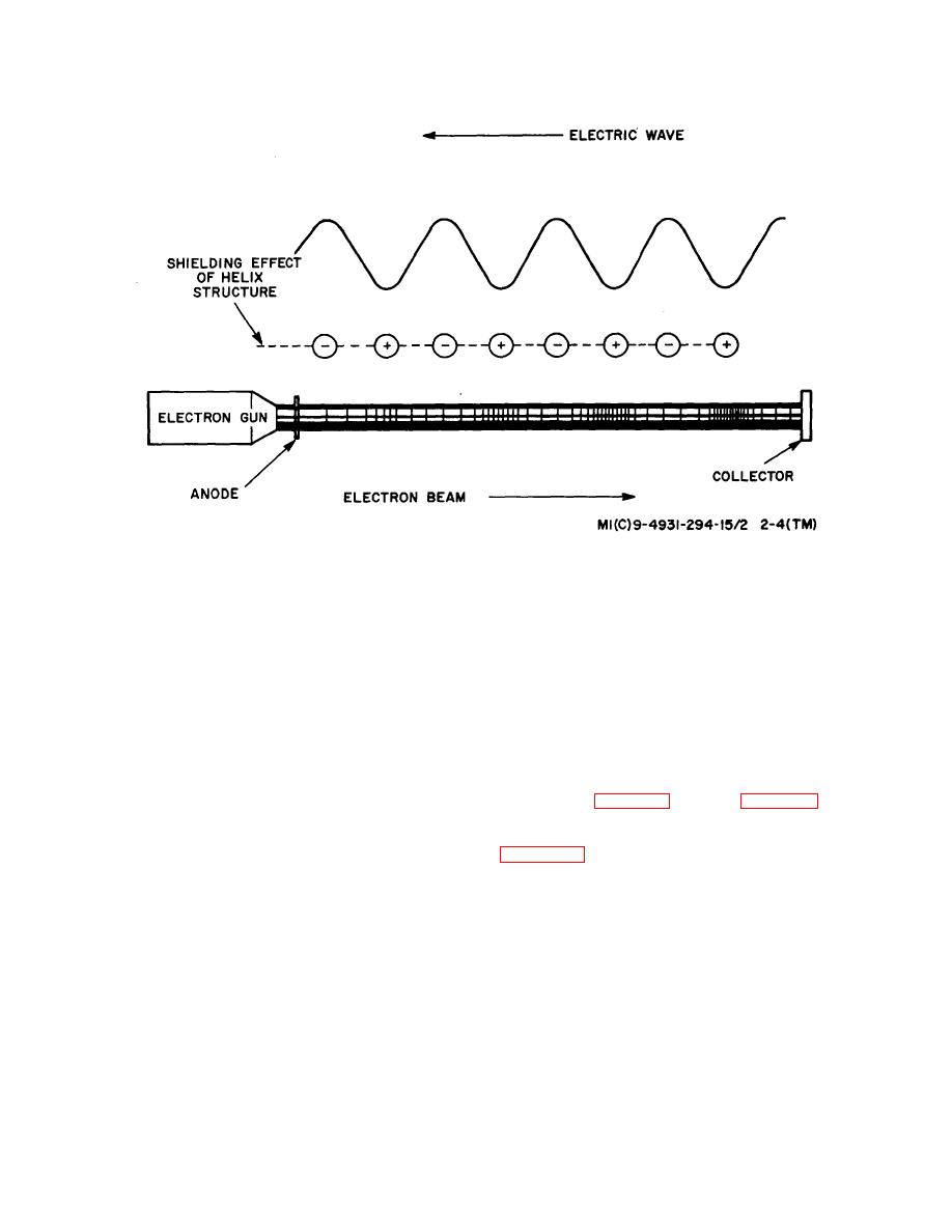
Figure 2-4. BWO Tube Operation.
from the beam. The density of the electron beam, and
the collector voltage is clamped at a constant value
therefore the number of electrons which are available to
above the helix voltage and the cathode is maintained at
contribute energy to the electric wave, is controlled by
ground potential, the output frequency is dependent,
the anode potential. By varying the anode voltage, the
primarily, on the helix voltage.
output power level may thus be adjusted.
(7) The BWO terminating resistance, located near
(5) Not all electrons in the beam are equally
the collector, absorbs any rf energy reflected from the rf
effective in producing bunching. Electrons in the center
output. If this rf energy were not absorbed it would be
of the beam experience nearly equal accelerating and
reflected again, causing interference with the rf wave
decelerating forces. Electrons must be sufficiently close
being generated. By absorbing the reflected wave, the
to the helix in order to be pulse modulated by the
frequency and power level variations are minimized.
shielding effect of the helix. As a result, hollow electron
(8) Typical performance curves of a BWO are
beams are usually employed to increase the beam
illustrated on figure 2-5 Part A of figure 2-5 indicates that
efficiency.
the output frequency increases with increasing helix
(6) Since the amplification process causing
voltage. In general this curve is exponential. Part B of
oscillation in a BWO tube depends upon the approximate
synchronism between the velocity of the electric wave
megahertz per volt decreases as the output frequency of
and the electron beam, the frequency of the output signal
the BWO is increased. Modulation sensitivity is defined
is determined primarily by the potential existing between
as the frequency
the
cathode
and
the
collector.
Since
2-6

