
voltage from the BWO power supply and applied to the
the 1- to 2-GHz range. This signal is then applied
BWO tube located in the rf head. e. In order to achieve
through another 3-db attenuator to the preselector. The
continuous tunability below 1 GHz, the phase-lock input
PRESELECTOR TUNE control is adjusted to select one
from the rf head is not applied directly to the mixer. This
of the harmonics in the 1- to 2-GHz range. This signal is
phase-lock signal is applied through a 3-db attenuator to
then applied to the mixer and is processed in the same
manner as described above.
Section II. THEORY OF MASUREMENT TECHNIQUES
2-10. Introduction
2-11. Frequency Measurement of an Active Source
This section contains theory discussions on the test
setups used when operating microwave calibration test
measurement is a digital counter. Since the counter can
set AN/USM-234 to perform the following functions:
measure frequencies below 15 GHz only, two test setups
frequency measurement of an active source, frequency
are required to cover the complete test set range from
calibration of a passive device, measurement of rf
500 MHz to 40 GMz. One test setup measures the
power, magnitude of reflection coefficient measurements
frequency directly up to 15 GHz, and the other setup
between 1 and 40 GHz, VSWR measurements below 1
employs a frequency multiplier as a means of extending
GHz, and attenuation measurements. Each discussion
the frequency range to 40 GHz.
also includes an analysis of the inherent errors affecting
b. Circuit Analysis for Measurements Below 15 GHz.
the accuracy of the measurement. Each measurement
is illustrated by means of a block diagram.
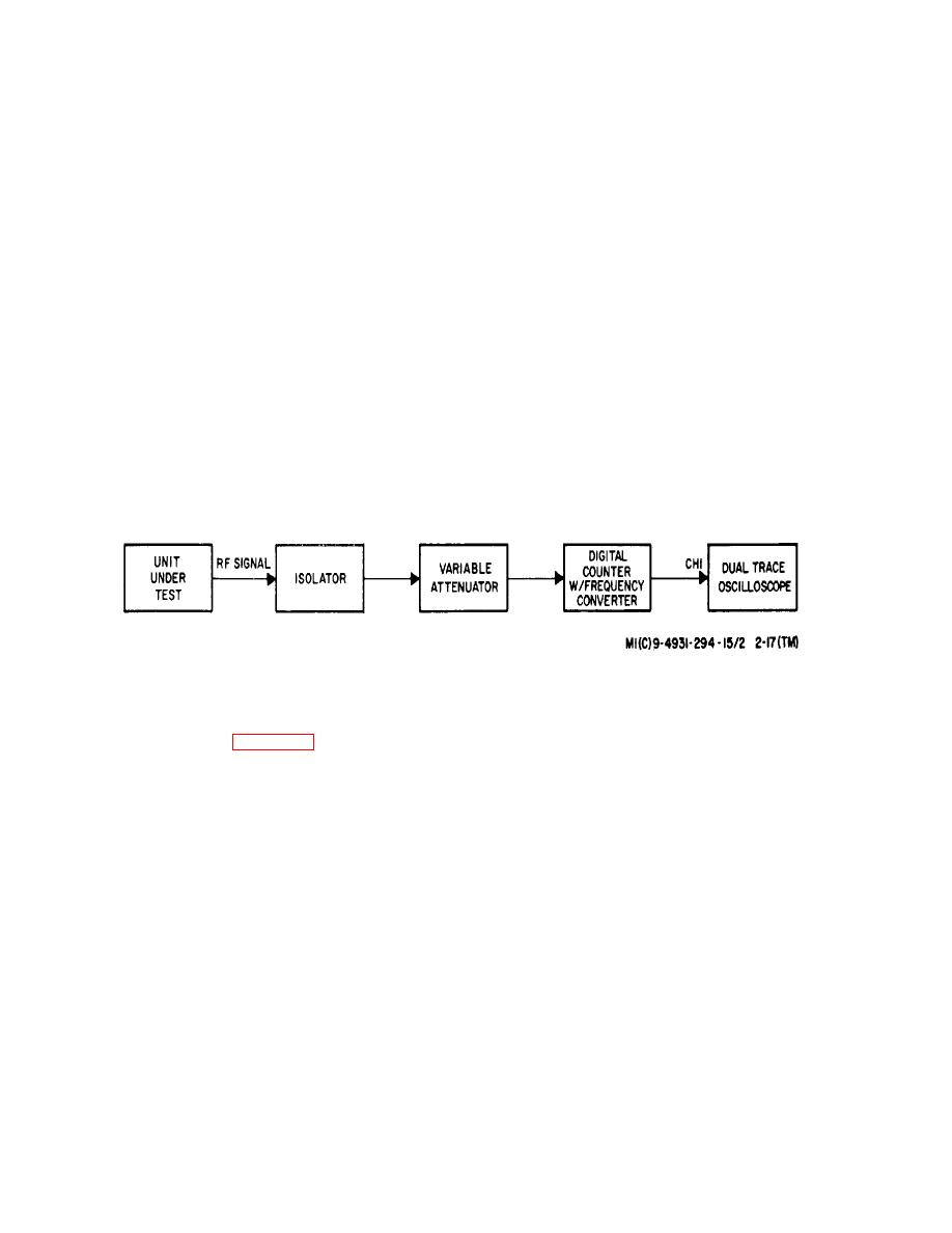
(1) The rf signal (CW, am, fm, or
Figure 2-17. Frequency Measurement of an Active Source Below 15 GHz, Block Diagram.
pulsed) to be measured is applied through an isolator
(3) The major sources of error inherent to
and a variable attenuator (figure 2-17) to the input of the
frequency measurements are due to the inaccuracies of
frequency converter, which is part of the digital counter.
the internal time base, the gating error and overdriving or
The video output of the frequency converter is applied to
underdriving of the digital counter.
the channel 1 input of the dual trace oscilloscope.
(a) The error due to time base inaccuracy is
(2) The isolator prevents the transmission of
directly related to the stability of the master oscillator in
reflected signals from the digital counter to the rf input.
the digital counter, which is 3 parts in 109 per day.
(b) The gating error can cause a possible error
The variable attenuator is used to obtain a digital counter
input level between -30 to -10 dbm in the frequency
of one count.
For high frequencies, this error is
range from 500 MHz to 10 GHz and -7 dbm in the
insignificant, but at lower frequencies it may become
frequency range from 10 to 15 GHz. This prevents the
significant to the accuracy of the indication. This error
digital counter from being overdriven or underdriven.
can be reduced by a factor of 10 by extending the
The oscilloscope is used to provide a larger and more
measurement time interval. A longer timing interval is
readily discernible display than the cathode ray tube in
obtained by repositioning the TIME BASE switch on the
the frequency converter.
digital counter.
(c) Overdriving or underdriving the
2-21

