
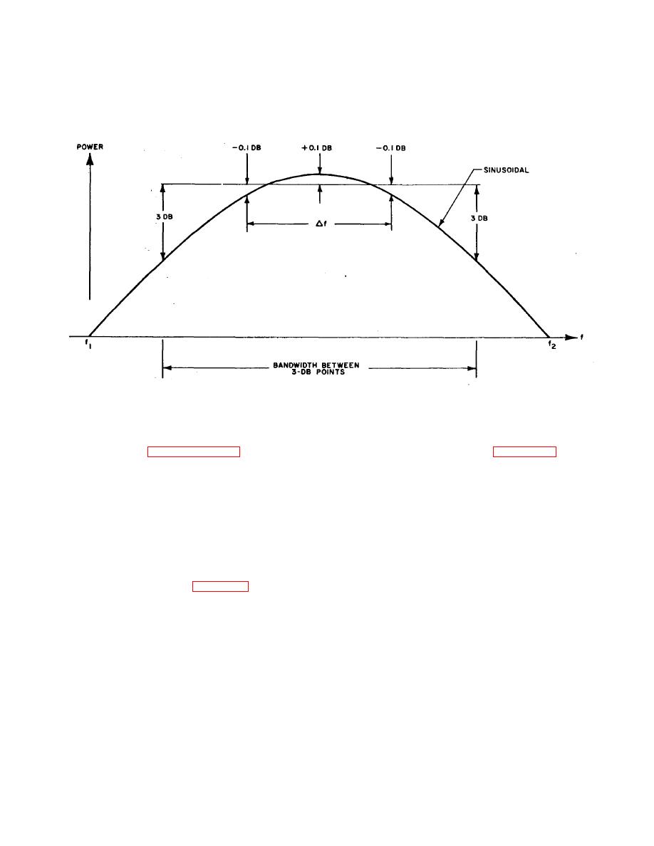
of the frequency response curve which, in turn, is a
which a passive device can be calibrated, but also in a
function of the signal input to the passive device. In
less accurate calibration. Calibration of passive devices
general, a greater tolerable variation of input power to
over a narrow bandwidth therefore results in greater
the passive device results in a greater bandwidth over
accuracy.
IF THE PERMISSIBLE MODE CURVE FLATNESS IS :O.I DB
Figure 2-20. Effects of Signal Input Level on Calibration of a Passive Device.
(5) Refer to paragraph 2-11 b for other
using the setup shown in figure 2-22. The power
measurement errors affecting the accuracy of the
meter is used with one of five thermistor mounts
measurement.
which collectively cover the complete frequency range
b. Circuit Analysis for Measurements Above 12.4
from 0.5 to 40 GHz. Basically, each thermistor mount
GHz. The measurement setup for the calibration of
contains two pairs of matched thermistors. The rf
power is applied to one thermistor pair and causes its
passive devices above 12.4 GHz is similar to that
temperature and resistance to change in accordance
described in a above, with the following exceptions:
with the applied power.
The second pair of
(1) Signal source no. 2 is set to a subharmonic
thermistors is isolated from the rf field and therefore
of signal source no. 1, since the upper frequency
responds to changes in ambient temperature only.
measurement limit of the digital counter is 15 GHz. The
The thermistor mount is connected to the power
frequency marker from signal source no. 2 is then
meter through a cable. Two self-balancing bridge
applied to a frequency multiplier (figure 2-21)..
circuits in the power meter measure the change in
(2) The frequency of the marker is obtained by
resistance of the thermistor pairs. The first thermistor
multiplying the digital counter indication by the
pair is connected in one bridge circuit which senses
appropriate harmonic number.
the rf power level. The second thermistor pair is
connected in the other bridge circuit which corrects
2-13. Rf Power Measurements
the meter readings for ambient
a. Rf power measurements
are
performed
2-25

