
TM 9-4935-294-15/2
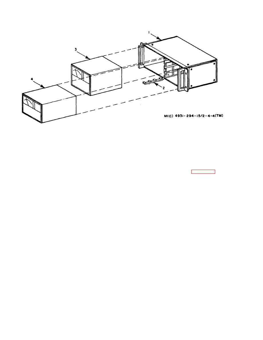
1--Combining case--79231833--Power meter--7910462--3
2--Joining lock (part of item 1)
4--SWR meter--7910160--3
Figure 4-4. Disassembly and assembly of combining case.
(1) Removal of power meter and SWR meter. To
Note. For disassembly and assembly of the combining
case, refer to paragraph d below.
remove the power meter and SWR meter from the
combining case, refer to figure 4-4 and proceed as
(1) Remove four retaining screws (3) and four
follows:
washers (4) securing graphic display system (2) to
(a) Release joining lock (2).
combination case (1).
(b) Remove power meter (3) and SWR
(2) Slide graphic display system (2) forward until
the slides lock in full forward position, then lift slide
meter (4) from combining case (1).
locking latches and remove unit from combination
(c) Disconnect power line cords from
case.
combination case receptacles.
(3) Disconnect power supply line cord from
(2) Reinstallation of power meter and SWR meter. To
combination case receptacle.
reinstall the power meter and SWR meter in the
b. Removal of Combining Case. To remove the
combining case, refer to figure 4--4 and reverse the
combining case from combination case no. 2, refer to
order of removal.
figure 4--3 and proceed as follows:
(1) Remove four retaining screws (6) and four
4-11. Removal and Reinstallation of Micro--
washers (4) securing combining case (5) to combination
wave Receiver in Combination Case
case (1).
No. 3.
(2) Lift and remove combining case (5).
a. Removal. To remove the microwave receiver from
(3) Disconnect power supply line cord
combination case no. 3, refer to figure 4--5 and proceed
from the combination case receptacle.
as follows:
c. Reinstallation. To reinstall the graphic display
(1) Remove four retaining screws (3) and washers
system and combining case, refer to figure 4--3 and
(4) to detach microwave receiver (2) from combination
reverse the order of removal.
case (1).
d. Disassembly and Assembly of Combining
(2) Slide microwave receiver (2) forward until the
Case.
slides lock in full forward position,
4-6

