
TM 9-4935-294-15/2
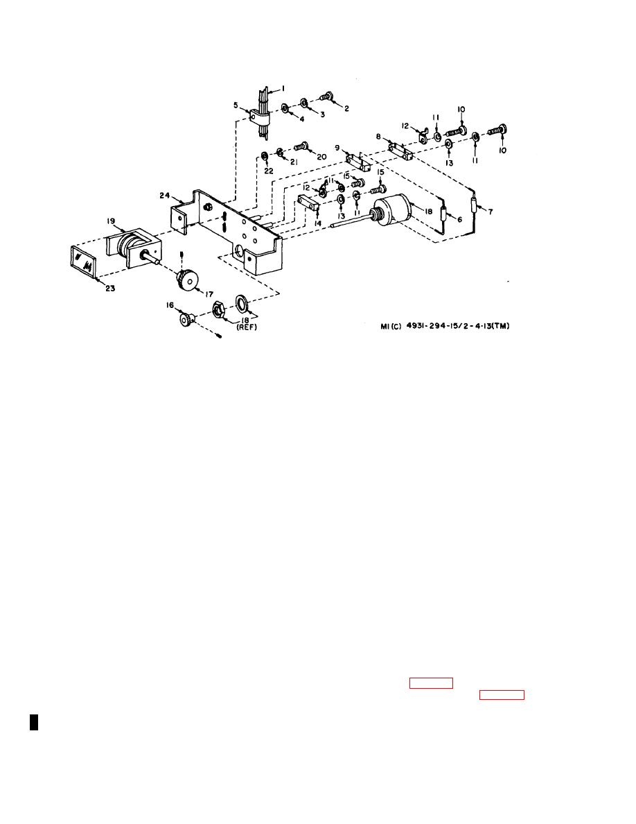
12--Lug, solder--7923256--1
1--Harness--7923085--1
13--Washer, flat, round, steel, cd-
2--Screw, machine, pan hd, no. 6-
MS27183--2
32, 1/2 in. Ig, UNC--2A--MS-
14--Resistor, variable (R1505)-
35206-230
7923072--3
3--Washer, lock, split, helical, no.
15--Screw, machine, pan hd, no. 2-
6--MS35338--41
56, 5/8 in. lg, UNC--2A-
4--Washer, flat--MS27183--5
MS35206--208
5--Clamp, loop--plastic, wire sup-
16--Gear, helical--7923058--10
port--MS25281--5
17--Gear, helical--792305--2
6--Resistor, fixed (R1506)--RN20-
18--Resistor, variable, 10, turn (R1-
X7500F
502) --7923070
'7--Wire, bare, tinned, 3 in. Ig-
19--Counter assy--7923057
7923212--2
20--Screw, machine, pan hd, no. 4-
8--Resistor, variable (R1501)-
40, 3/8 in. Ig, UNC--2A-
7923072--4
MS35206215
9--Resistor, variable (R1503)-
21--Washer, lock, split, helical, no.
7923072--1
2--MS35338--40
10--Screw, machine, pan hd, no. 2-
22--Washer, flat, round, steel, cd-
56, 7/8 in. Ig, UNC--2A-
MS27183--3
MS35206--210
23--Window--7923060
11--Washer, lock, split, helical, no.
24--Bracket assy--7923041--1
2--MS35338--39
Figure 4-16. Counter Assembly 7923056--2, Exploded View.
_________________________________________________________________________________________________
(9) Place BWO tube (14) within rf head chassis (41)
(12) Connect adapter (20) to the N connector of
and aline tube brackets with mounting holes in the
balun.
chassis. Attach with four screws (16), washers (5) and
(13) Install clamp (10) and attach to bracket (23)
nuts (15).
with screw (9), washer (12), and nut (11).
(10) Connect and resolder the blue harness lead to
(14) Connect and solder the yellow and green
terminal 2 on the dispersion PC board assembly (refer to
harness leads to connector bracket assembly (8) solder
1, fig. 4--12).
lug (refer to 17, fig. 4-12).
(11) Install connector bracket assembly (8, fig. 4--
(15) Install side cover (1, fig. 4-14) with 10 screws
14) on rf head chassis (41) with two screws (9). Apply
(2).
sealing compound 10528558 to screws (9), then tighten.
Change 1 4-24

