
TB 9-4935-558-50-1
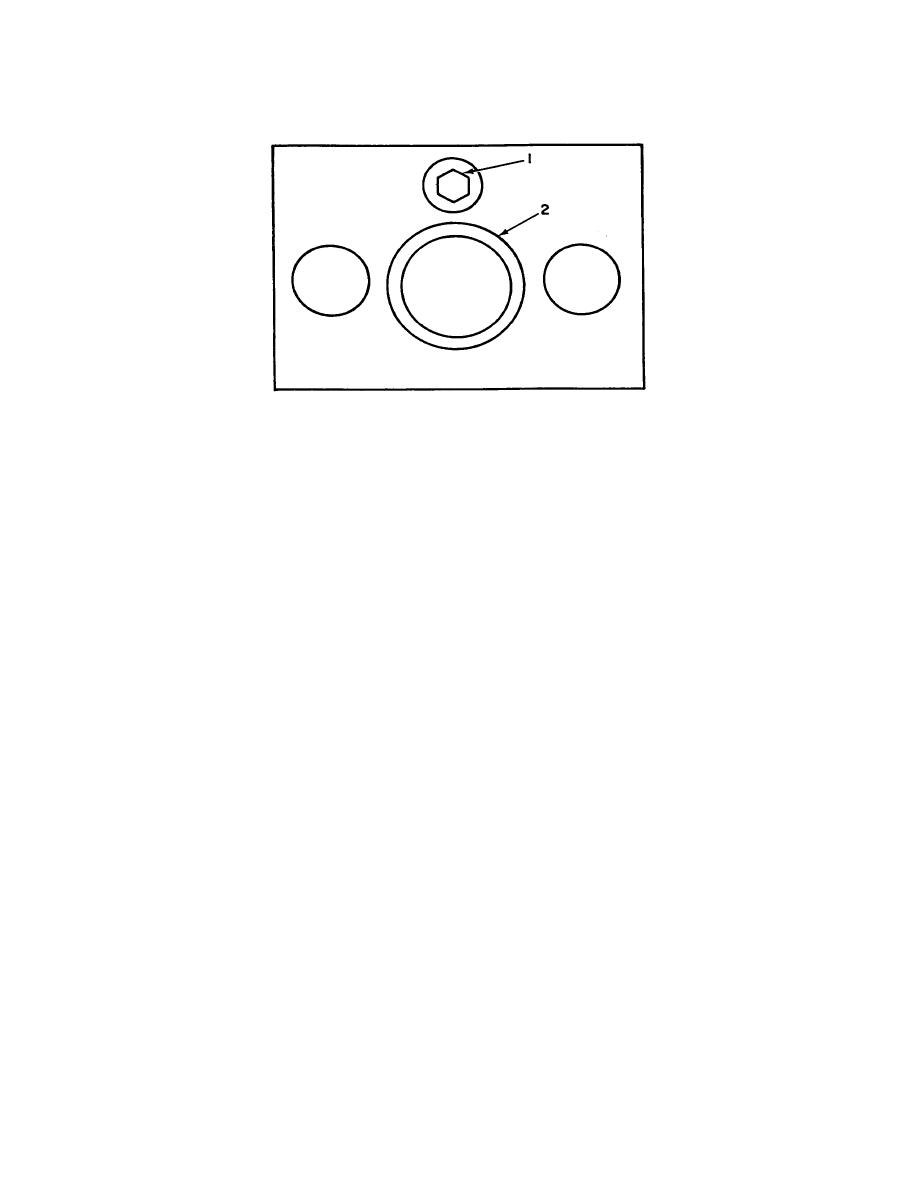
1 - Adjusting screw
2 - Slider
Figure 1. Top view test instrument.
SECTION IV
NOTE
Unless otherwise specified, verify the results of each test and
take corrective action whenever the test requirement is not
met before continuing with the calibration.
8. Force Dimension and Load Check
a. Performance Check
(1) Place the weight table (A3) and 94 lbs. weight on the slider. TI force gage will
indicate between 90.0 and 100.0. Record reading. If force gage reads out of tolerance
return complete TI to depot.
(2) Remove weights and weight table from TI.
(3) Place C-clamp (B2) in a vise with C-clamp in a vertical position, with the
adjusting screw on C-clamp on top. Place the TI on the C-clamp with TI slider on bottom
and tighten until the force gage indicates the same reading as recorded in step (1) above.
(4) Position the micrometer frame (A1) on the TI and measure the internal depth of
the slider. The micrometer frame will indicate the dimension on the calibration .001 inch.
if not, perform b below. Disregard first figure (whole number) on calibration label when
reading micrometer.
4
