TM 9-4935-294-15/2
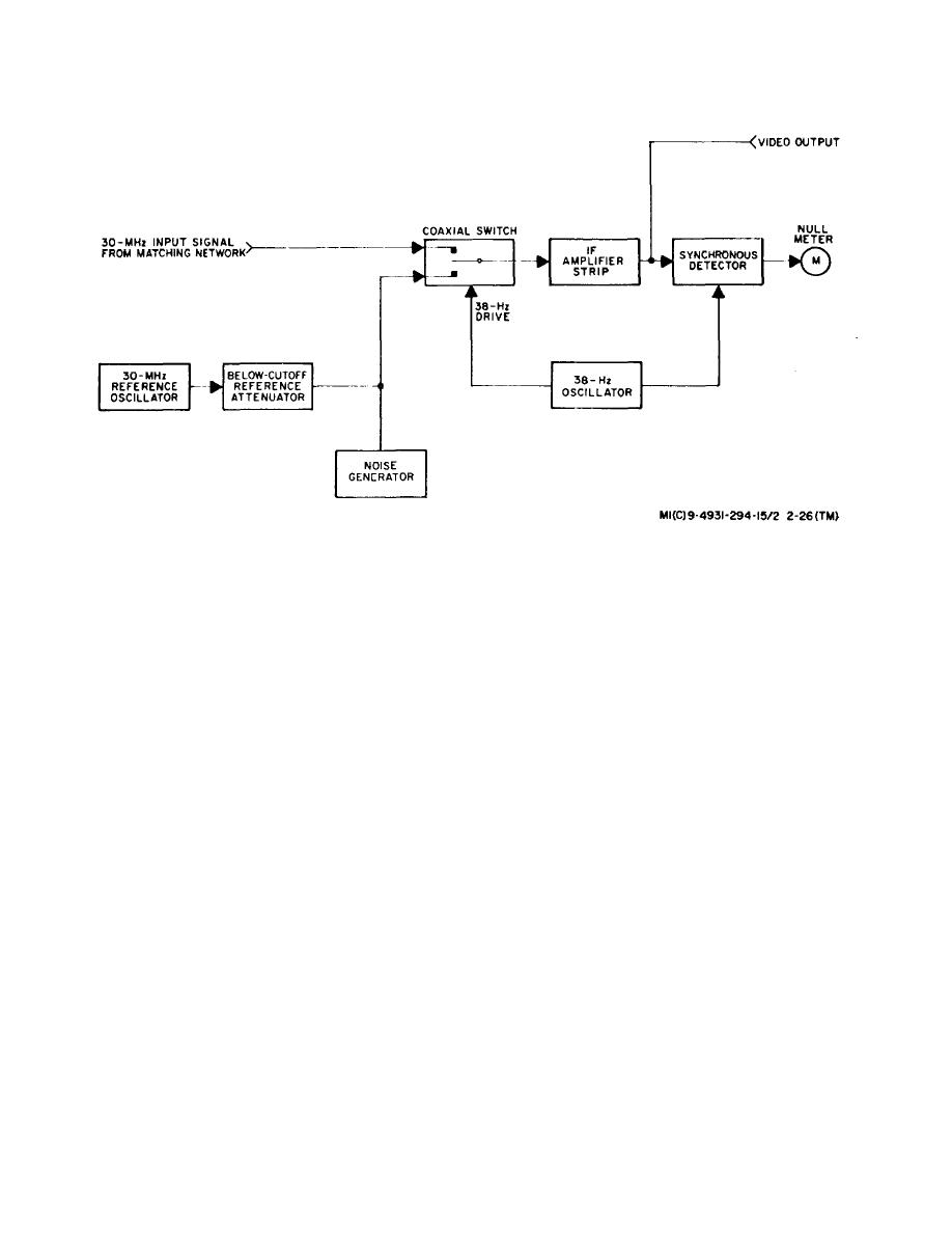
Figure 2-26. Microwave Receiver, Simplified Block Diagram.
(4) Leakage error. RF leakage, which by-passes
tenuator used as the reference attenuator in the
microwave receiver is calibrated to an accuracy of
the attenuator under test, can be a prime source of error
+0.005 db +0.01% of setting. Errors due to backlash can
if the test setup is not adequately isolated. The most
be eliminated by always approaching the reference
common source of rf leakage is caused by radiation from
attenuator setting from the same direction.
poorly fitting flanges, tuner slots, and mixer cables. If the
(2) Signal source instability.
Errors due to
leakage path is maintained 40 db higher than the
frequency and amplitude instability are minimized by the
measured attenuation, the leakage error will not exceed
microwave receiver AFC loop and the leveling capability
0.1 db. The use of double shielded cables, and cover
of the signal source which maintains the output within
and choke flanges or gaskets between mating flanges
+0.01 db.
will further aid in reducing the rf leakage error.
(3) Mixer non-linearities. Slight mixer non-linearities
(5) The overall accuracy of attenuation
measurements over the frequency range from 500 MHz
may exist at high-signal levels due to the corresponding
to 40 GHz is +0.3 db from O to 10 db, +(1% of
small local oscillator to signal source signal-level ratio.
attenuation value +0.2)db from 10 to 60 db, and + (4% of
These errors may be minimized by maintaining the local
attenuation value -1.6) db from 60 to 80 db
oscillator signal level 15 db (at least 10 db) above the
measurement if all operating procedures and
signal
level
of
the
signal
source.
precautions are adhere to.
Change 1 2-22


